Exposure apparatus of belt type workpiece and focusing regulation method thereof

A focus adjustment and exposure device technology, which is applied in photolithography process exposure devices, microlithography exposure equipment, optics, etc., can solve problems such as unestablished, and achieve the effects of preventing productivity reduction and correcting changes.

Active Publication Date: 2009-02-04
USHIO DENKI KK
View PDF1 Cites 14 Cited by
  • Summary
  • Abstract
  • Description
  • Claims
  • Application Information

AI Technical Summary

Problems solved by technology

Therefore, when developing the pattern for focus adjustment and performing focus adjustment by aligning the microscope, it...

Method used


Image

  • Exposure apparatus of belt type workpiece and focusing regulation method thereof
  • Exposure apparatus of belt type workpiece and focusing regulation method thereof
  • Exposure apparatus of belt type workpiece and focusing regulation method thereof

Examples


Embodiment Construction

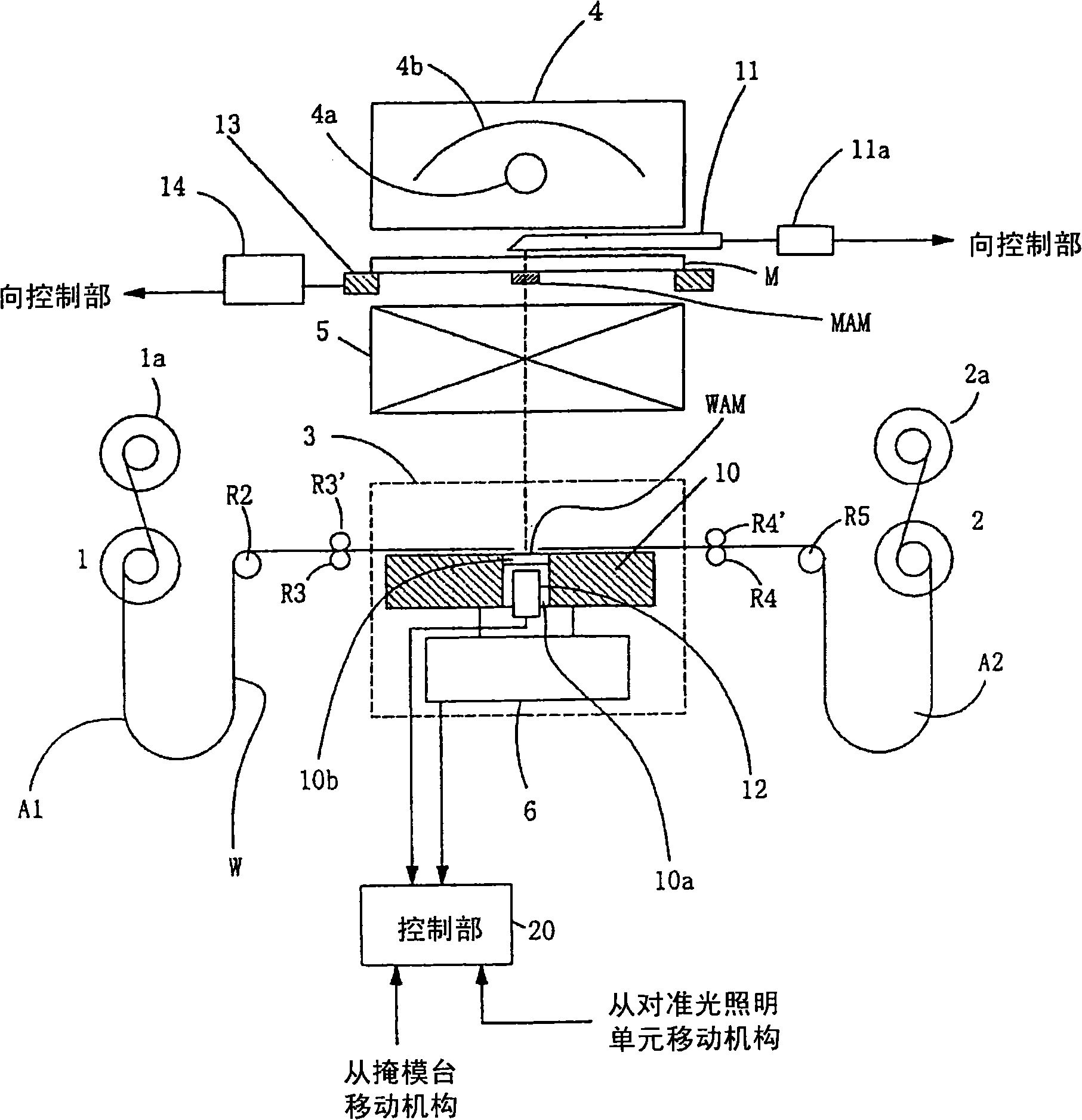
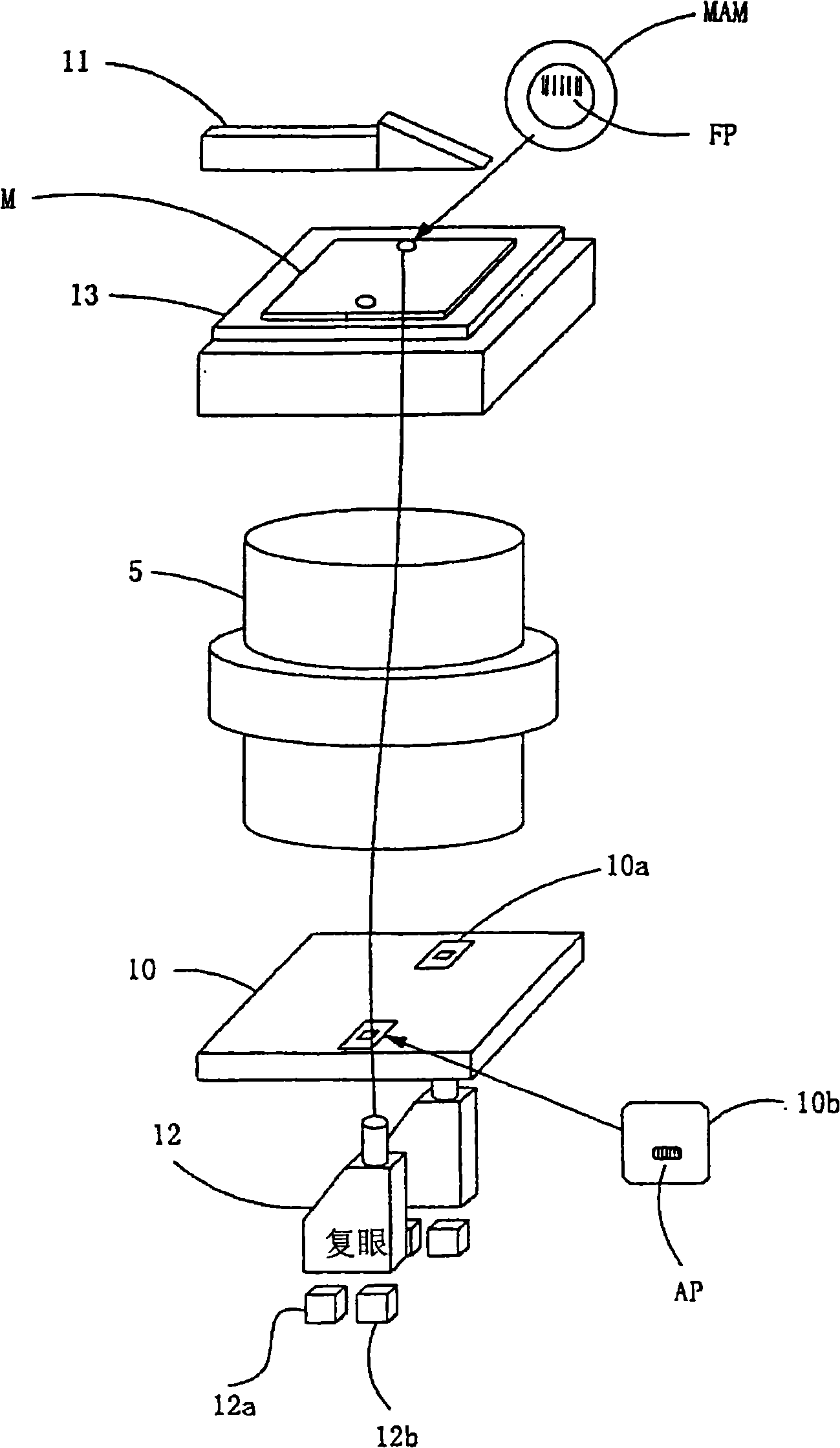
[0078] exist figure 1 , figure 2 The device configuration of the embodiment of the present invention is shown. figure 1 The overall configuration of the exposure apparatus for a belt-shaped workpiece according to this embodiment is shown, figure 2 expressed in figure 1 In the shown apparatus, a drawing showing parts of an alignment light illumination means, a mask stage, a projection lens, a work stage, and an alignment microscope is extracted.

[0079] exist figure 1 , figure 2 In this case, the mask stage 13 is moved at least in the Z direction (optical axis direction, vertical direction in the drawing) by the mask stage moving mechanism 14 .

[0080] The workpiece table 10 is also moved in the optical axis direction (Z direction, vertical direction in the drawing) by the workpiece table moving mechanism 6 .

[0081] The mask stage 13 and the work stage 10 move with the position of the focal length (design value) of the projection lens 5 as the origin position i...


PUM


Abstract

The project of the invention is to achieve focusing regulation during exposure treatment, does not need to increase a lighting unit or a developing unit, and can regulate focus in a short time. A pattern formed in a mask (M) is projected in a band workpiece (W), and a focusing regulation pattern (FP) for a projection lens is formed inside a mask target (MAM) of the mask (M) in an exposure device for exposing the band workpiece. Moreover, a light transmission component (10b) is arranged on a communicating pore or a nick (10a) of a workbench (10), so as to form a focusing regulation pattern (AP) for an aligning microscope. The aligning microscope (12) detects the aligning mark of the mask and the band workpiece, aligns the mask (M) and the band workpiece (W), and then, the aligning microscope (12) detects the focusing regulation pattern (FP) for the projection lens and the focusing regulation pattern (AP) for the aligning microscope and regulates the focus.

Description

technical field [0001] The present invention relates to an exposure device for forming a pattern on a long tape-shaped workpiece of TAB (Tape Automated Bonding) or FPC (Flexible Printed Circuit) and a focus adjustment method of the exposure device. Background technique [0002] In display panels such as liquid crystals, mobile phones, digital cameras, and IC cards, etc., thin film circuit boards in which integrated circuits are mounted on resin films such as polyester or polyimide with a thickness of about 25 μm to 125 μm are used. In the manufacturing process of the thin film circuit board, for example, it is a tape-shaped workpiece with a width of 160 mm, a thickness of 100 μm, and a length of several hundreds of m, and is usually wound on a reel. [0003] In addition, in the film circuit board, a conductor (for example, copper foil) is pasted on the above-mentioned resin film. The manufacture of thin-film circuit boards involves repeating, for example, 4 to 5 times the p...

Claims


Application Information

Patent Timeline
IPC IPC(8): G03F7/207G03F7/20G03F9/02H05K3/00
Inventor 柴田清孝
Owner USHIO DENKI KK
Why Eureka
Try Eureka