
Monitoring device for strained condition of pressure dispersion anchorage cable based on force transmitting board

A technology of stress state and monitoring device, which is applied in the direction of tension measurement, etc., can solve the problems of anchor plate damage, anchor plate 40 damage, and inability to monitor the force state, etc., and achieves easy operation, wide application, and intuitive test principle Effect

Inactive Publication Date: 2009-02-11
INST OF ROCK AND SOIL MECHANICS - CHINESE ACAD OF SCI +1
View PDF4 Cites 5 Cited by
  • Summary
  • Abstract
  • Description
  • Claims
  • Application Information

AI Technical Summary

Problems solved by technology

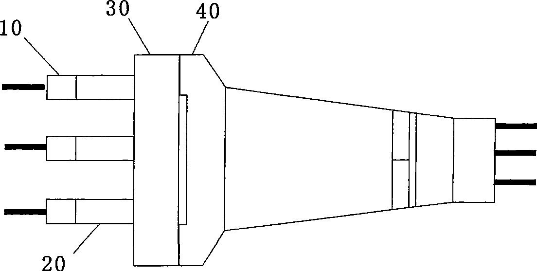
[0007] However, in practical applications, it is found that there is a phenomenon that the anchor plate 40 is destroyed when the prestress is applied.
This is because the anchor plate 40 is a cast iron body, and the anchor plate 10 will be embedded in the depression of the anchor plate 40 when it is installed, so that the main force-bearing part is the depression when the anchor cable is stretched, and the anchor plate 40 One part is thicker and will not be damaged when the prestress is applied to the anchor cable; but when installing the pressure dispersion type anchor cable stress state monitoring device, in order to meet the installation of the anchor cable dynamometer 20, a The expansion plate 30, because the diameter of the expansion plate 30 is larger than the concave diameter of the original anchor plate 40, the force-bearing part changes when the anchor cable is stretched, and the thinner part of the anchor plate 40 bears the pressure, so that the anchor plate 40 It may be damaged under pressure, and normal stress state monitoring cannot be carried out

Method used


Image

  • Monitoring device for strained condition of pressure dispersion anchorage cable based on force transmitting board
  • Monitoring device for strained condition of pressure dispersion anchorage cable based on force transmitting board
  • Monitoring device for strained condition of pressure dispersion anchorage cable based on force transmitting board

Examples


Embodiment Construction

[0032] Below in conjunction with accompanying drawing and embodiment the present invention is further described:

[0033] 1. Overall

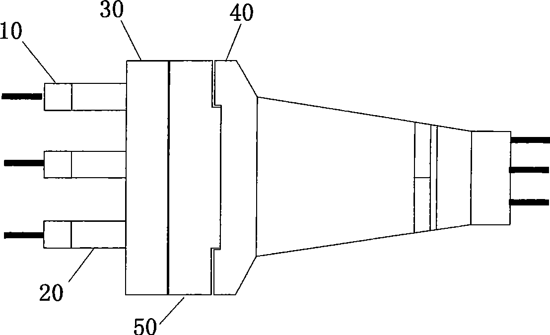
[0034] Such as figure 2 , the device includes an anchor plate 10, an anchor cable dynamometer 20, an expansion plate 30 and an anchor backing plate (40), and a force transmission plate 50 is provided;

[0035] Its location and connection relationship are:

[0036] After the anchor backing plate 40 of the anchor cable is installed, the anchor backing plate 40, the force transmission plate 50, the expansion plate 30, the anchor cable gauge 20 and the anchor plate 10 are connected in sequence.

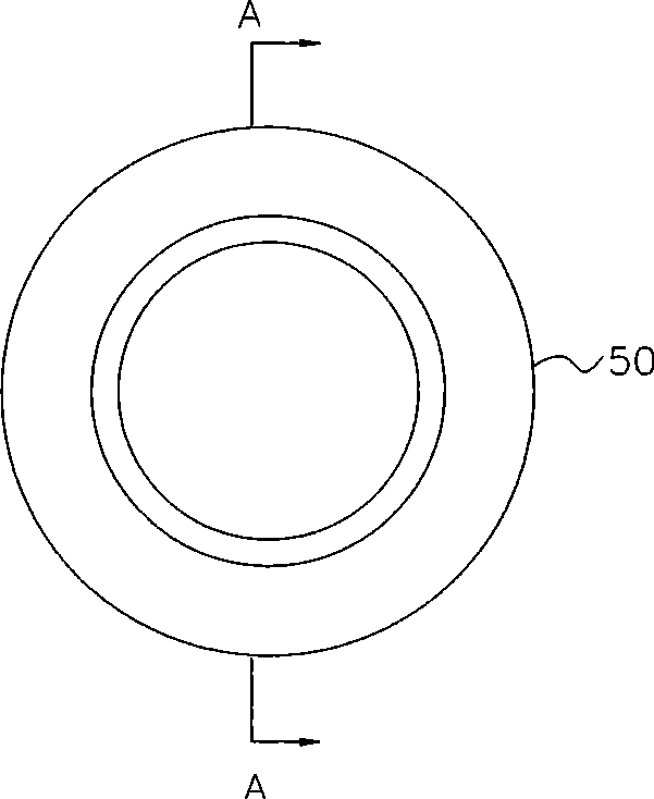
[0037] The force transmission plate 50 is a hollow thick circular plate provided with a circular boss.

[0038] 2. Related parts

[0039] 1. Force transmission plate 50

[0040] Such as image 3 , 4 , the end face of the force transmission plate 50 connected to the anchor pad 40 is provided with a ring boss, the thickness of the ring boss is slight...


PUM


Abstract

The invention discloses a pressure dispersion type anchor rope stress state monitoring device based on a force passing plate, relates to a anchor rope stress state monitoring device, mainly solves the force passing problem when the prestress between an expansion plate and an anchor backing plate is stretched and drawn, and effectively avoids the problem that the anchor backing plate can be damaged when the anchor rope is stretched and drawn when the pressure dispersion type anchor rope stress state is monitored. The monitoring device comprises an anchor plate (10), an anchor rope force meter (20), an expansion plate (30), an anchor backing plate (40) and a force passing plate (40). The anchor backing plate (40), the force passing plate (50), the expansion plate (30), the anchor rope force meter (20) and the anchor plate (10) are connected in sequence. The force passing plate (50) is provided with a round ring bass hollow thick round plate. The invention can avoid the phenomena that the anchor backing plate (40) can be damaged, and is suitable for monitoring the artificial side slopes or sliding slopes reinforced by the pressure dispersion anchor rope in the projects, such as high ways, railways, mines, hydropower stations, and the like.

Description

technical field [0001] The invention relates to a monitoring device for the stressed state of the anchor cable, in particular to a pressure dispersion type monitoring device for the stressed state of the anchor cable based on a force transmission plate; The problem of force transmission during tension can effectively avoid the problem that the anchor plate may be damaged when the anchor cable is tensioned when the force state monitoring is carried out on the pressure dispersion anchor cable. Background technique [0002] From the perspective of natural disasters, the loss caused by landslides to all countries in the world may be second only to earthquakes and tsunamis. Many countries, including China, are countries with relatively serious landslide disasters. According to statistics in recent years, the loss of economic construction and people's life and property caused by geological disasters caused by slope instability is nearly 30 billion yuan in our country every year. ...

Claims


Application Information

Patent Timeline
IPC IPC(8): G01L5/04
Inventor 沈强路为陈从新张高朝肖国峰张家铭李宗长童华军
Owner INST OF ROCK AND SOIL MECHANICS - CHINESE ACAD OF SCI
Learn More