Electric connector automatic separating apparatus

An electrical connector, automatic separation technology, applied in the parts of the connection device, connection, coupling device, etc.

Inactive Publication Date: 2010-07-28
CHINA AVIATION OPTICAL-ELECTRICAL TECH CO LTD
View PDF0 Cites 0 Cited by
  • Summary
  • Abstract
  • Description
  • Claims
  • Application Information

AI Technical Summary

Problems solved by technology

[0002] The plug and socket of some electrical connectors need to realize the automatic separation of the plugging direction while moving perpendicular to the plugging direction. Some existing electrical connectors automatically The separation device realizes the automatic separation of the plug and the socket through the action of electrical components (electromagnets), but the electrical components of this type of separation device will have a negative impact on the electrical connector or other components, while the automatic separation of purely mechanical actions The size of the device is large and cannot be automatically returned. It is difficult to separate the plug and socket at the same time as the plug and socket move perpendicular to the plugging direction to achieve the plugging direction.

Method used


Image

  • Electric connector automatic separating apparatus
  • Electric connector automatic separating apparatus
  • Electric connector automatic separating apparatus

Examples


Embodiment Construction

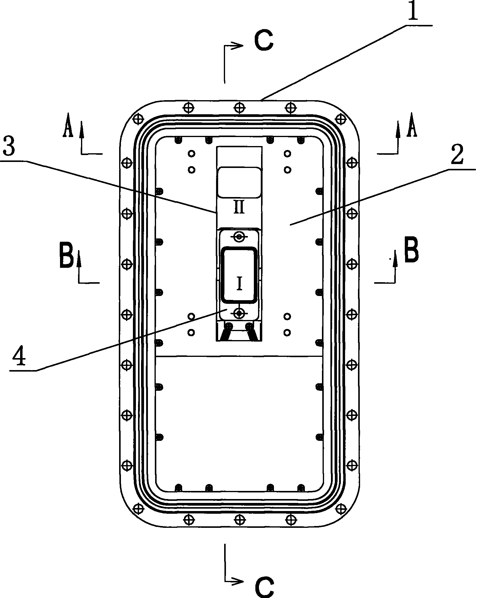
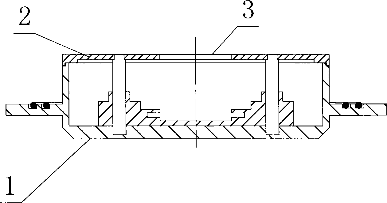
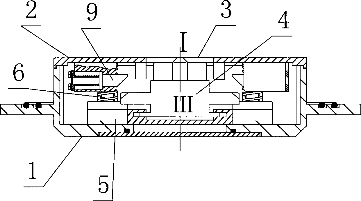
[0022] Such as Figure 1 to Figure 7 As shown, an automatic separation device for electrical connectors of the present invention includes a housing 1, and the panel 2 of the housing 1 is provided with a capacitive connector. The plug-in port 3 is moved in the vertical direction at the same time, and the plug-in port 3 has an insertion position I and a separation position II. The insertion position I corresponds to the connector seat 4 and moves out of the plug-in port 3. When the connector is plugged in The separation position II corresponds to the position where the connector seat 4 is submerged in the insertion port 3, and the fully submerged position of the connector seat 4 in the direction of unplugging and insertion corresponding to the insertion position I is the return position III. The guide rail 5 is movably assembled in the body 1 through the guide column 6 guided along the direction of connector plugging and unplugging. Correspondingly, the connector seat 4 is mova...


PUM


Abstract

The invention discloses an automatic separating device of an electric connector, and comprises a shell body. A connector base is arranged on the shell body; an insertion separating port is arranged on a panel of the shell body; a guide rail is movably assembled on a guiding device which guides in the plugging direction of the connector in the shell body; the connector base is movably assembled onthe guide rail in the guiding direction of the guide rail; an automatic guide rail return mechanism which drives the guide rail to move to the return position in the plugging direction is arranged onthe guide rail; an automatic connector base return mechanism which drives the connector base to move from the separation position to the splicing position is arranged on the connector base; and a retaining tongue locking mechanism for preventing the connector base from moving to the return position is arranged on the shell body in the splicing position of the insertion separating port. The power components of the separating device is used for skillful unlocking by utilizing external force from vertical and plugging direction; the separating action is realized by the guide rail return mechanism; the unlocking and the separating action can be completed instantly. Therefore, the separating device has the advantages of reliable linkage and no interference on an external system.

Description

technical field [0001] The invention relates to the technical field of electrical connectors, in particular to an automatic separation device for electrical connectors. Background technique [0002] The plug and socket of some electrical connectors need to realize the automatic separation of the plugging and unplugging direction while moving perpendicular to the plugging and unplugging direction. The automatic separation action of the socket, but the electrical components of this type of separation device will have a negative impact on the electrical connector or other components, and the automatic separation device with purely mechanical action is large in size and cannot automatically return, so it is difficult to connect the plug The momentary separation of the plugging direction is achieved while the socket is moving perpendicular to the plugging direction. Contents of the invention [0003] The object of the present invention is to provide an automatic disconnecti...

Claims


Application Information

Patent Timeline
Patent Type & Authority Patents(China)
IPC IPC(8): H01R13/635H01R13/639
Inventor 孙晓军
Owner CHINA AVIATION OPTICAL-ELECTRICAL TECH CO LTD
Why Eureka
Try Eureka