Linkage device and DR shooting machine

A linkage device and linkage technology, applied in medical science, diagnosis, patient positioning for diagnosis, etc., can solve the problems of being too firm, not easy to separate, and the linkage mechanism is not tightly clamped.

Active Publication Date: 2019-05-10
河北天地智慧医疗设备股份有限公司
View PDF7 Cites 0 Cited by
  • Summary
  • Abstract
  • Description
  • Claims
  • Application Information

AI Technical Summary

Problems solved by technology

[0003] The invention proposes a linkage device and a DR filming machine, which solves the problem that

Method used


Image

  • Linkage device and DR shooting machine
  • Linkage device and DR shooting machine
  • Linkage device and DR shooting machine

Examples


Example Embodiment

[0042] The technical solutions in the embodiments of the present invention will be clearly and completely described below in conjunction with the embodiments of the present invention. Obviously, the described embodiments are only a part of the embodiments of the present invention, rather than all the embodiments. Based on the embodiments of the present invention, all other embodiments obtained by those of ordinary skill in the art without creative work shall fall within the protection scope of the present invention.

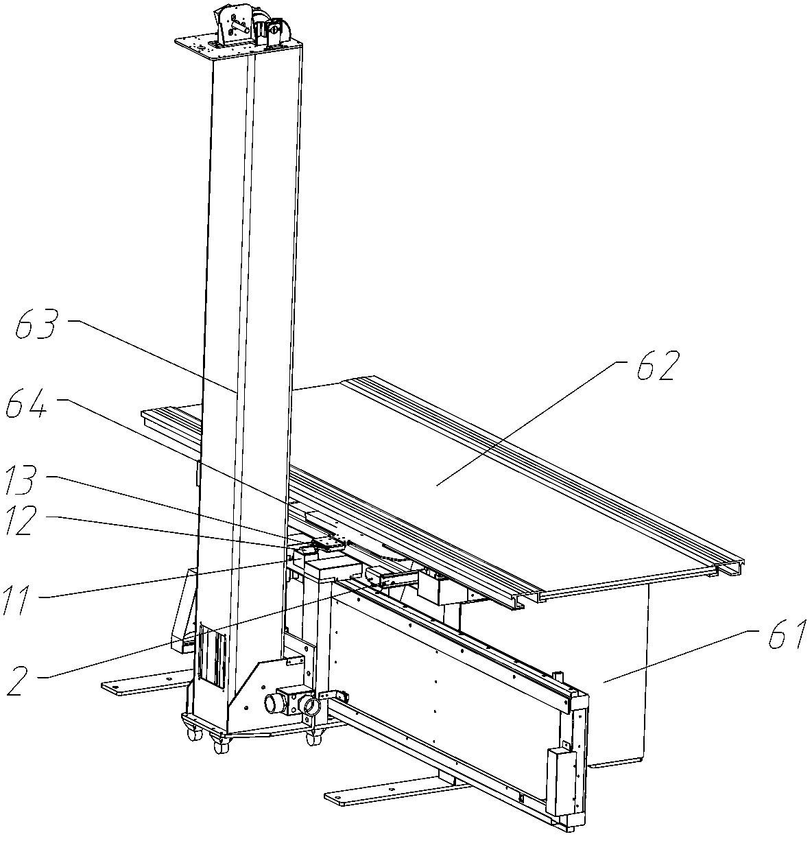
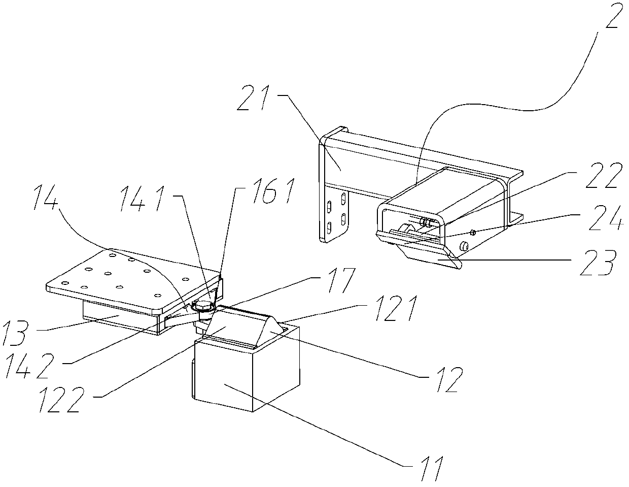
[0043] Such as Figure 2~8 As shown, a linkage device includes a guide seat 11 and a mounting block 13;

[0044] The linkage block 12 is slidably arranged on the guide seat 11 in the vertical direction;

[0045] The linkage positioning block 14 is slidably arranged on the mounting block 13 in the longitudinal direction, the linkage positioning block 14 is provided with a groove 16 and both sides of the groove 16 are provided with buffer slopes 161;

[0046] The first el...


PUM


Abstract

The invention belongs to the technical field of linkage equipment, and provides a linkage device and a DR shooting machine. The linkage device comprises a guide base, a mounting block, a linkage block, a linkage positioning block and a first elastic component; the linkage block is slidably arranged on the guide base in the vertical direction; the linkage positioning block is slidably arranged on the mounting block in the longitudinal direction and provided with a groove, and buffering slopes are arranged at the two sides of the groove; the first elastic component is arranged on the mounting block and used for providing longitudinal elastic force for the linkage positioning lock, the guide base is used for being connected with a first linkage part, and the mounting block is used for being connected with a second linkage part. According to the linkage device and the DR shooting machine, the problem in the prior art that a linkage mechanism cannot be connected or is not easily separated due to excessive fastness is solved.

Description

technical field [0001] The invention belongs to the technical field of linkage equipment, and relates to a linkage device and a DR filming machine. Background technique [0002] When shooting medical images, it is often necessary to link the column and the bed detector tray. In practical applications, the linkage positioning block is often used to clamp the linkage bearing to achieve the purpose of linkage, such as figure 1 Shown is an existing linkage mechanism, including a linkage block a, a linkage positioning block b, a groove c set on the linkage and positioning block b, and a linkage bearing d set on the linkage block a to rotate, the direction of the arrow shown is the linkage direction of the linkage block a and the linkage positioning block b. If the depth of the groove c is small, the locking of the linkage positioning block b to the linkage bearing d is not firm, and the linkage state often ends early. If the depth of the groove c is too large, the linkage The cl...

Claims


Application Information

Patent Timeline
IPC IPC(8): A61B6/00A61B6/04
Inventor 杨彦光耿亚洲戚少波
Owner 河北天地智慧医疗设备股份有限公司
Why Eureka
Try Eureka