Testing bench frame and method for engine with variable compression ratio

A technology of test bench and engine, which is applied in the direction of engine testing, machine/structural component testing, measuring devices, etc. It can solve problems such as few results and complex structure, achieve simple structure, expand the scope of application, and realize the effect of visualization

Active Publication Date: 2009-02-18
CHERY AUTOMOBILE CO LTD
View PDF0 Cites 12 Cited by
  • Summary
  • Abstract
  • Description
  • Claims
  • Application Information

AI Technical Summary

Problems solved by technology

[0004] At present, the research on variable compression ratio engines has been relatively common in foreign countries, but there are relatively few achievements that can realize the function of variable compression ratio, and the structure is complex
Especially in the aspect of test bench system, foreign technology is relatively mature, but there is basically no similar technology in China

Method used


Image

  • Testing bench frame and method for engine with variable compression ratio
  • Testing bench frame and method for engine with variable compression ratio
  • Testing bench frame and method for engine with variable compression ratio

Examples


Embodiment 1

[0038] Embodiment 1: the connection and fixing method of the cylinder.

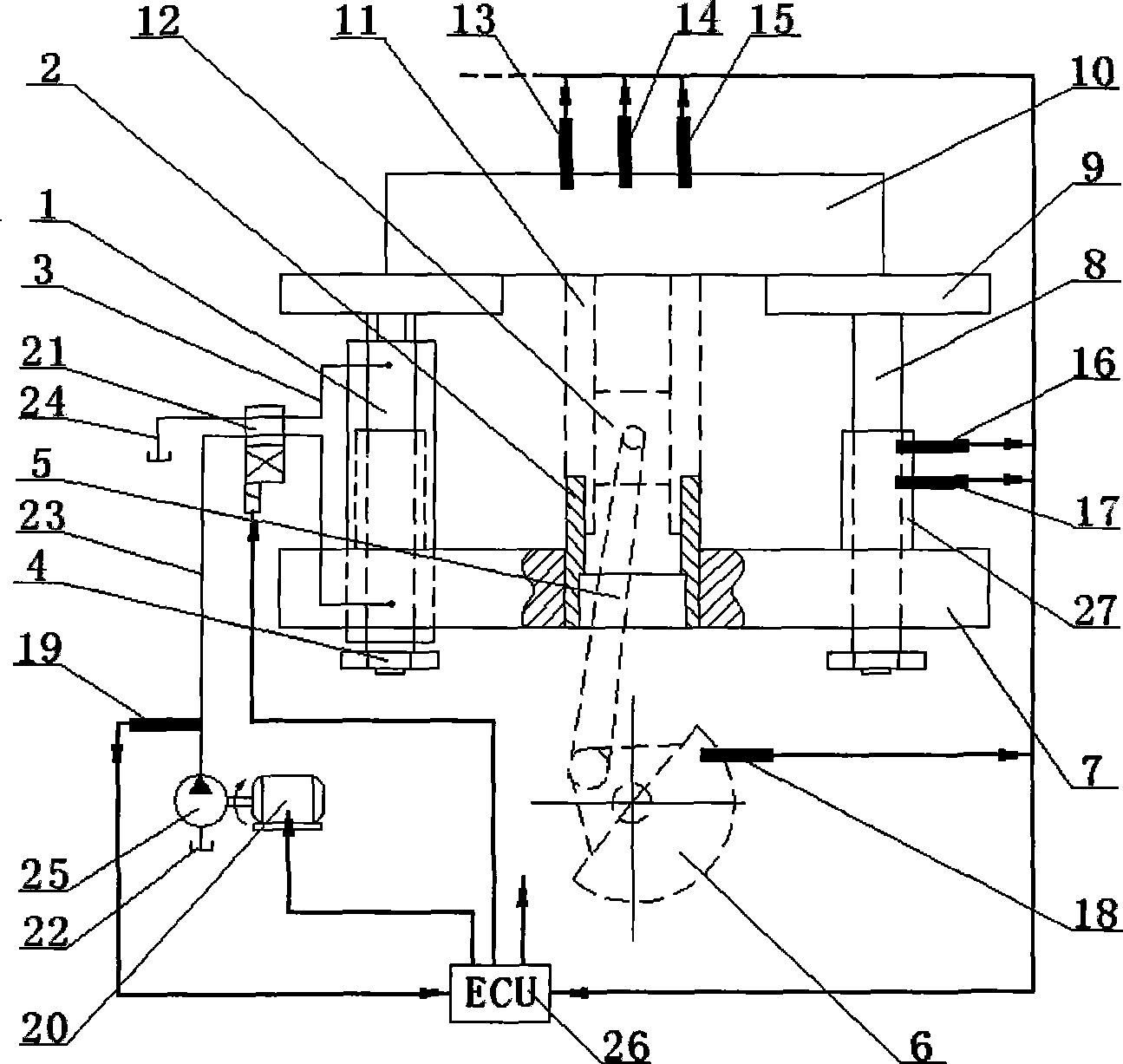
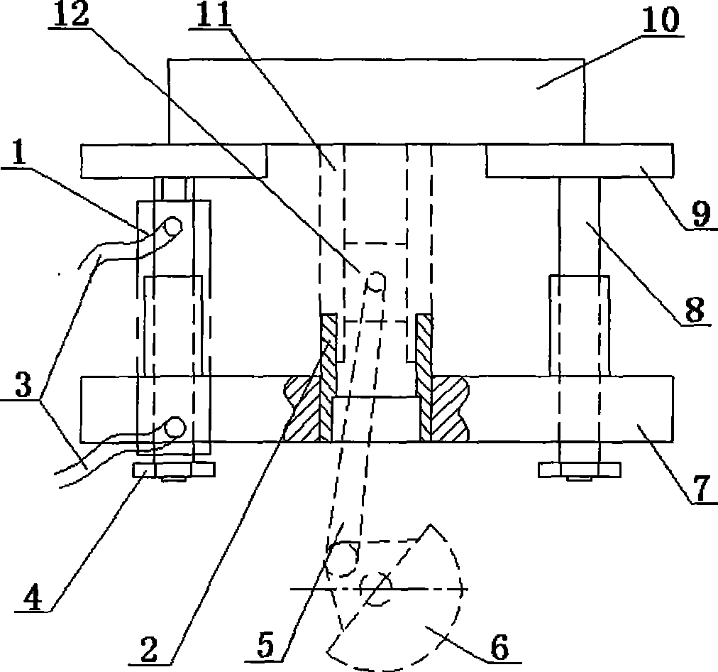
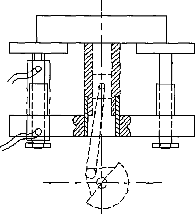
[0039] Two support plates are arranged horizontally, one of which is the lower support plate 7, which is fixed on the test bench, the cylinder block 11 is connected to the lower support plate 7 through the cylinder block support sleeve 2, and the cylinder block 11 is fixed to the cylinder block support sleeve 2 Connection, the cylinder block support sleeve 2 and the lower support plate 7 are axially slidingly connected, and the upper end of the cylinder block 11 is fixedly connected with the upper support plate 9 .

[0040] At the bottom of the hydraulic cylinder 1, lock it with a limit nut 4 to prevent the movement range from being too large and slipping out from the lower support plate 7.

[0041] The above structure ensures the relative movement between the cylinder block 11 and the lower support plate 7 to realize the change of the compression ratio.

Embodiment 2

[0042] Embodiment 2: crankshaft installation position and connection and fixing method.

[0043] The axis of the crankshaft 6 is fixed on the test bench, and is connected with the piston 12 through the connecting rod 5 under the lower support plate 7 .

[0044] Since the position of the axis of the crankshaft 6 relative to the test bench is constant, and the cylinder block 11 is adjustable up and down, the adjustment of the cylinder compression ratio is realized.

Embodiment 3

[0045] Embodiment 3: The connection structure of the upper end of the cylinder block 11 (that is, the cylinder head assembly 10).

[0046] The connection structure between the upper end of the cylinder block 11 and the upper support plate 9 is as follows: a cylinder head assembly 10 is provided, and is fixedly connected with the cylinder block 11 and the upper support plate 9 respectively.

[0047] The cylinder block 11 and the cylinder head assembly 10 are connected together by cylinder bolts. The first purpose of this connection is to seal the combustion chamber;


PUM


Abstract

The invention belongs to the technical field of automobile manufacturing technology and equipment and discloses an engine test bench with variable compression ratio; a hydraulic transmission system is arranged in the test bench; the support plates at both ends of a cylinder body (11) are connected through a hydraulic cylinder (1) in the hydraulic transmission system, namely, one support plate is connected with the hydraulic cylinder body, while the other support plate is connected with a hydraulic cylinder piston rod; and one of the support plates is fixed on the test bench. With the technical proposal, the invention can continuously achieve compression ratio changes and can shorten and determine the ideal compression ratio cycle of the engine; the invention can quickly obtain the influence parameters of the compression ratio to the engine combustion performance; the invention expands the application scope and can carry out the bench test for gasoline engines and diesel engines; and based on needs, the cylinder body can be made transparent so as to achieve combustion process visualization.

Description

technical field [0001] The invention belongs to the technical field of automobile manufacturing process equipment, and relates to automobile engine test equipment, more specifically, the invention relates to an engine test bench with variable compression ratio. In addition, the present invention also relates to the test method adopted by the engine test bench. Background technique [0002] With the more stringent automobile emission regulations and the improvement of customers' requirements on engine economy, improving the emission performance and fuel economy performance of engines has become the direction of efforts in the design and manufacture of automobiles for major automobile manufacturers. Its main methods focus on post-processing (external purification) and combustion optimization (internal purification). At present, very satisfactory results have been achieved in the aspect of external purification, such as SCR, DPF, etc., which can meet the standards of Euro 5 or...

Claims


Application Information

Patent Timeline
Patent Type & Authority Applications(China)
IPC IPC(8): G01M15/00G01M15/02
Inventor 黄前海
Owner CHERY AUTOMOBILE CO LTD
Why Eureka
Try Eureka