Testing bench frame and method for engine with variable compression ratio
A technology of test bench and engine, which is applied in the test of engine test bench, the field of engine test bench with variable compression ratio, can solve the problems of complex structure and few results, and achieve the expansion of application range, simple structure and control convenient effect
- Summary
- Abstract
- Description
- Claims
- Application Information
AI Technical Summary
Problems solved by technology
Method used
Image
Examples
Embodiment 1
[0038] Embodiment 1: the connection and fixing method of the cylinder.
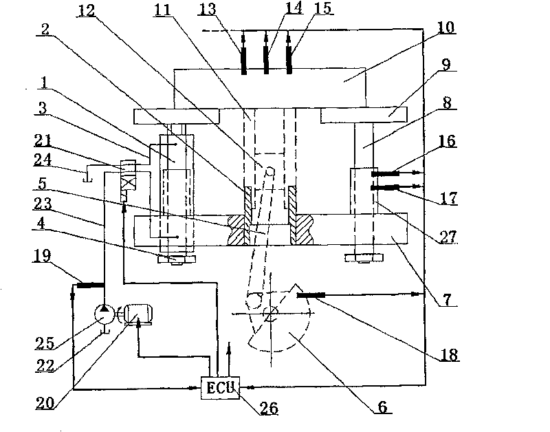
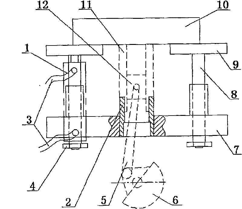
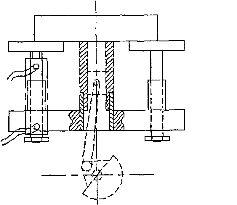
[0039] Two support plates are arranged horizontally, one of which is the lower support plate 7, which is fixed on the test bench, the cylinder block 11 is connected to the lower support plate 7 through the cylinder block support sleeve 2, and the cylinder block 11 is fixed to the cylinder block support sleeve 2 Connection, the cylinder block support sleeve 2 and the lower support plate 7 are axially slidingly connected, and the upper end of the cylinder block 11 is fixedly connected with the upper support plate 9 .
[0040] At the bottom of the hydraulic cylinder 1, lock it with a limit nut 4 to prevent the movement range from being too large and slipping out from the lower support plate 7.
[0041] The above structure ensures the relative movement between the cylinder block 11 and the lower support plate 7 to realize the change of the compression ratio.
Embodiment 2
[0042] Embodiment 2: crankshaft installation position and connection and fixing method.
[0043] The axis of the crankshaft 6 is fixed on the test bench, and is connected with the piston 12 through the connecting rod 5 under the lower support plate 7 .
[0044] Since the position of the axis of the crankshaft 6 relative to the test bench is constant, and the cylinder block 11 is adjustable up and down, the adjustment of the cylinder compression ratio is realized.
Embodiment 3
[0045] Embodiment 3: The connection structure of the upper end of the cylinder block 11 (that is, the cylinder head assembly 10).
[0046] The connection structure between the upper end of the cylinder block 11 and the upper support plate 9 is as follows: a cylinder head assembly 10 is provided, and is fixedly connected with the cylinder block 11 and the upper support plate 9 respectively.
[0047] The cylinder block 11 and the cylinder head assembly 10 are connected together by cylinder bolts. The first purpose of this connection is to seal the combustion chamber;
PUM
 Abstract
Description
Claims
Application Information
 - R&D
- Intellectual Property
- Life Sciences
- Materials
- Tech Scout
- Unparalleled Data Quality
- Higher Quality Content
- 60% Fewer Hallucinations
Browse by: Latest US Patents, China's latest patents, Technical Efficacy Thesaurus, Application Domain, Technology Topic, Popular Technical Reports.
© 2025 PatSnap. All rights reserved.Legal|Privacy policy|Modern Slavery Act Transparency Statement|Sitemap|About US| Contact US: help@patsnap.com


