Work transport device

一种输送装置、工件的技术,应用在操作装置、锻/压/锤装置、制造工具等方向,能够解决侧向空间需求大等问题,达到实现简单、空间小、侧向空间小的效果

Inactive Publication Date: 2010-04-21
HATEBUR UMFORMMASCHEN
View PDF9 Cites 0 Cited by
  • Summary
  • Abstract
  • Description
  • Claims
  • Application Information

AI Technical Summary

Problems solved by technology

The disadvantage of this type of clamp is that the two gripping arms are swiveled considerably outwards, resulting in a considerable lateral space requirement

Method used


Image

  • Work transport device
  • Work transport device
  • Work transport device

Examples


Embodiment Construction

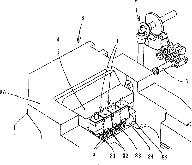
[0030] figure 1 The illustrated embodiment of the multi-stage molding machine 8 comprises four molding stations, from which a mold 81 , 82 , 83 and 84 can be seen in each case. The molds 81 , 82 , 83 , 84 are supported in a stationary mold carrier 85 which is indirectly connected to a machine frame 86 . A workpiece transport device with four grippers 1 is provided for transporting the workpieces 9 to the individual forming stations and then for transporting them away from there. The tongs 1 are on the one hand laterally displaceable, for which they are mounted on a transverse conveying unit 4 which is displaceable by means of a transverse conveying tube. On the other hand, the tongs 1 can be opened and closed and at the same time raised or lowered by means of a mechanism which will be described in more detail below. To open or close the tongs 1, a drive rod 3 displaceable in its longitudinal direction is provided, which is displaceable longitudinally by means of an adjustmen...


PUM


Abstract

A work transport device for a metal-forming machine comprises a pair of grips (1) which have two non-crossing gripper arms (11, 12) which are pivotable relative to one another and which each have a gripping end (111, 121) for gripping a workpiece (9). Each of the two gripper arms (11, 12) is coupled to a common guide head at the end (114) opposite the gripping end (111, 121) and to a separate link(13, 14) in a central region between the two ends. The two links (13, 14) are each rotatable about a fixed pivot (140). According to the invention, the fixed pivot (140) of the link (13, 14) of the one gripper arm (11, 12) is arranged closer to the other gripper arm (11, 12) than the fixed pivot (140) of the link (13, 14) of this other gripper arm (11, 12). As a result, the two gripper arms (11,12) are swung outwards to a smaller extent when being swung apart.

Description

technical field [0001] The invention relates to a workpiece conveying device for a forming machine. Background technique [0002] In today's common forming machines, the workpieces are usually deposited into forming stations by means of workpiece conveying devices and / or removed from these forming stations after forming. The multi-stage forming machine has multiple forming stations arranged in sequence, and a workpiece is processed in sequence at each forming station. In this case, the workpieces are transported between the individual forming stations by means of a workpiece conveyor. [0003] Known workpiece transport devices comprise a plurality of grippers with which the workpieces in the individual forming stations are simultaneously gripped, conveyed and then released again. For this purpose, the grippers are jointly driven in machine rhythm by a drive. [0004] There are various types of clamps in the prior art. For example, DE 35 23 323 A1 discloses a tongs which ...

Claims


Application Information

Patent Timeline
Patent Type & Authority Patents(China)
IPC IPC(8): B21K27/04
CPCB21K27/04
Inventor D·鲁赫蒂
Owner HATEBUR UMFORMMASCHEN
Why Eureka
Try Eureka