Vertical cleaner
A vacuum cleaner and vertical technology, which is applied in the field of hard pipe ash-proof structure, can solve the problem of dust leakage at the interface between the hard pipe and the suction head, and achieve the effect of improving dust collection efficiency and saving electric energy.
Active Publication Date: 2011-01-05
ECOVACS ROBOTICS (SUZHOU ) CO LTD
View PDF0 Cites 0 Cited by
- Summary
- Abstract
- Description
- Claims
- Application Information
AI Technical Summary
Problems solved by technology
The purpose of the present invention is to overcome the problem of dust leakage between the hard pipe and the suction head interface in the prior art, and provide a more efficient upright vacuum cleaner
Method used
View moreImage
Smart ImageViewing Examples
Examples
Embodiment Construction
Login to View More PUM
 Abstract
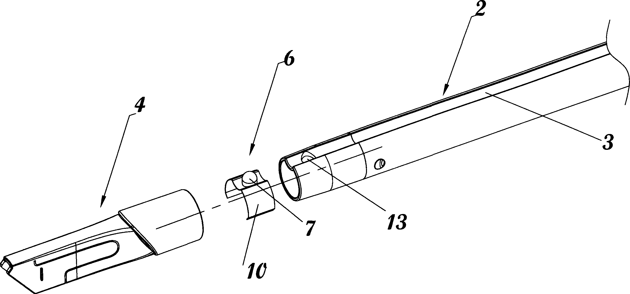
The invention relates to a vertical type dust collector including a vertical type dust collector body, a dust collector rigid tube connected with the body, and a suction head used for being connected with the rigid tube; a retaining groove is formed on the rigid tube and axially extending along the rigid tube; a retaining pin is matched with the retaining groove and arranged on the body; an elastic mechanism is arranged at an end part of the rigid tube connected with the suction head; the elastic mechanism includes a bulge which can extend the radial expansion of the rigid tube; the bulge is arranged in the retaining groove; when the rigid tube is connected with the suction head, the outside surface of the bulge is abutted against the inner wall surface of the suction head. Through addingthe elastic mechanism into the retaining groove, the dust collector can be cleaner due to the prevention of dust leakage by blocking the clearance formed by the rigid tube and the suction head with the bugle when the rigid tube is used for being connected with the suction head for dust collection; moreover, since the clearance formed by the rigid tube and the suction head can be blocked, the dustcollection efficiency of the dust collector can be improved, and the electrical energy can be saved.
Description
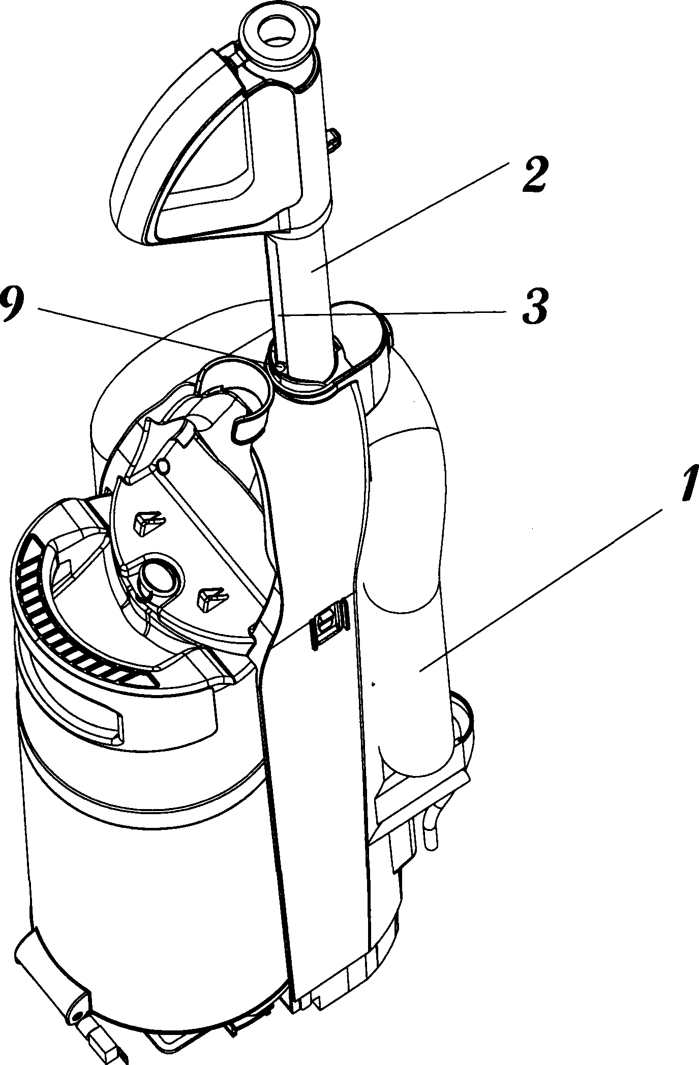
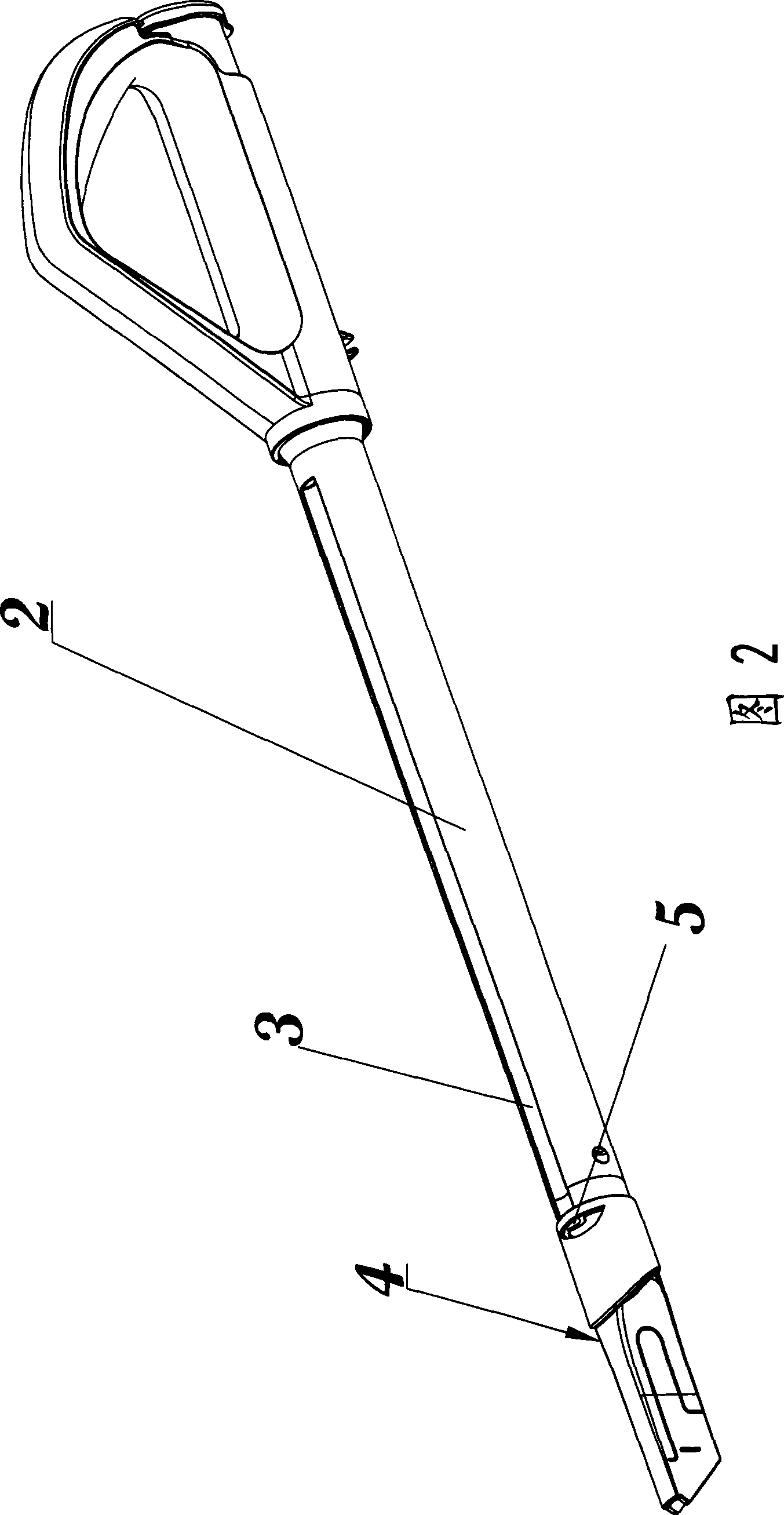
upright vacuum cleaner technical field The invention belongs to the field of upright vacuum cleaners, in particular to a hard pipe dust-proof structure of the upright vacuum cleaner. Background technique Most of the existing upright vacuum cleaner products are shown in Figure 1 below, including: the upright vacuum cleaner body 1, the hard tube 2 connected to the body, in some cases, the hard tube part shown in the figure can be used as an extension tube to connect One end of the tube, and the other end of the hard tube is connected to the dust suction head 4 to clean up the dust; when the upright vacuum cleaner is upright, the hard tube is only connected to the body, not as a part of the dust suction channel of the vacuum cleaner, in order to prevent The hard tube rotates freely on the body, so the hard tube is provided with a detent groove 3 for preventing the rotation of the hard tube, and correspondingly, the body is provided with a detent pin 9. When the vacuum cleaner...
Claims
Login to View More Application Information
Patent Timeline
 Patent Type & Authority Patents(China)
IPC IPC(8): A47L5/00A47L9/00A47L9/02
Inventor 刘凯
Owner ECOVACS ROBOTICS (SUZHOU ) CO LTD
Features
- R&D
- Intellectual Property
- Life Sciences
- Materials
- Tech Scout
- Unparalleled Data Quality
- Higher Quality Content
- 60% Fewer Hallucinations
Learn More Browse by: Latest US Patents, China's latest patents, Technical Efficacy Thesaurus, Application Domain, Technology Topic, Popular Technical Reports.
© 2025 PatSnap. All rights reserved.Legal|Privacy policy|Modern Slavery Act Transparency Statement|Sitemap|About US| Contact US: help@patsnap.com


