
Electronic display screen system, method and system for correcting electronic display screen brightness

A technology of brightness correction and display screen, applied in the field of display screen, can solve the problems that need dozens of hours to complete, consume a lot of time and human resources, and achieve the effect of reducing time and improving efficiency

Active Publication Date: 2009-03-04
NANTONG GEMEI IND CNC EQUIP CO LTD
View PDF0 Cites 26 Cited by
  • Summary
  • Abstract
  • Description
  • Claims
  • Application Information

AI Technical Summary

Problems solved by technology

For an electronic display screen composed of millions of light-emitting elements, assuming that the actual luminance values ​​of 10 pixels, that is, 10 light-emitting elements are measured in one second, it takes dozens of hours to adjust an electronic display screen, and the entire calibration process takes a lot of time. substantial time and human resources

Method used


Image

  • Electronic display screen system, method and system for correcting electronic display screen brightness
  • Electronic display screen system, method and system for correcting electronic display screen brightness
  • Electronic display screen system, method and system for correcting electronic display screen brightness

Examples


Embodiment 1

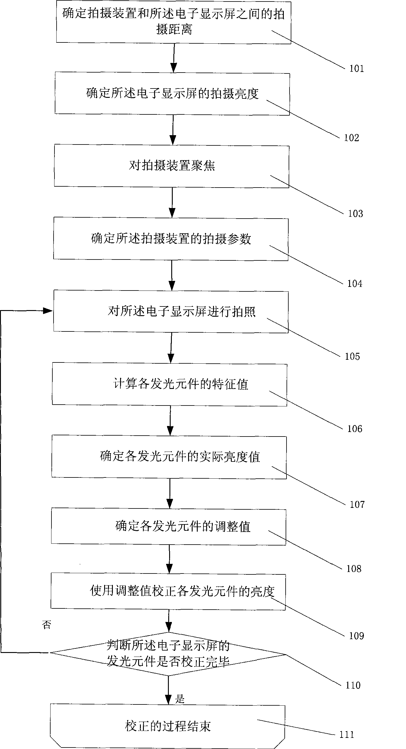
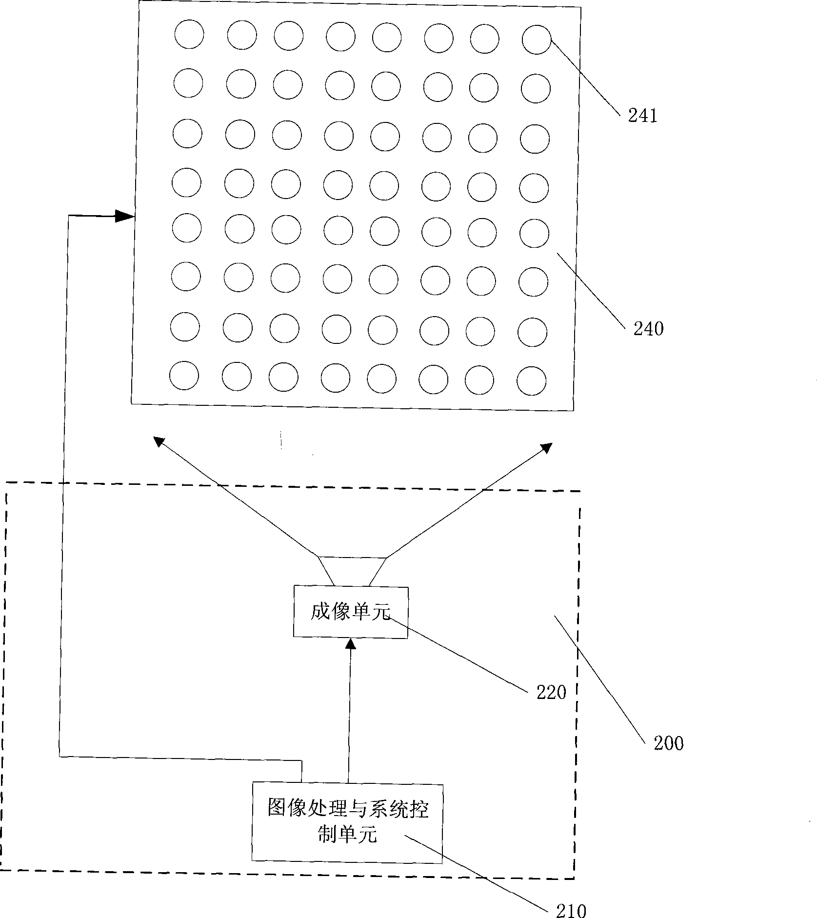
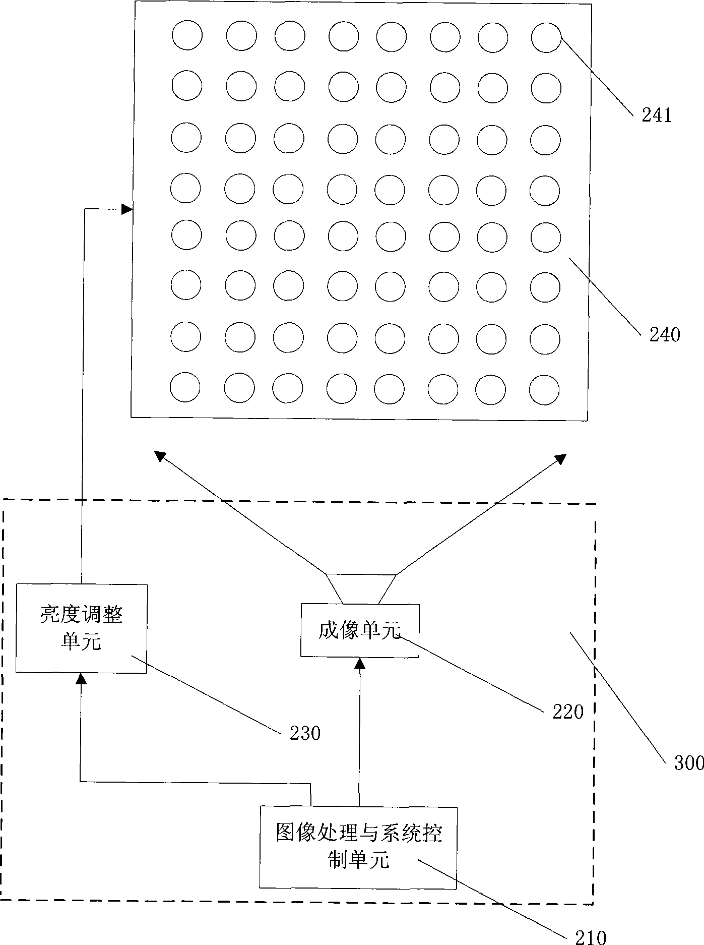
[0026] The method for adjusting the brightness of an electronic display screen provided by the present invention first obtains the characteristic values ​​of images of a plurality of light-emitting elements by taking pictures of the lighted electronic display screens; then uses the difference between the characteristic values ​​of the images and the actual brightness values ​​of each light-emitting element The functional relationship between each light-emitting element is determined to determine the actual brightness value of each light-emitting element; then the adjustment value of each light-emitting element is obtained through the difference between the actual brightness value of each light-emitting element and the target brightness value; finally, the adjustment value of each light-emitting element is obtained The brightness of each light-emitting element is adjusted to achieve the purpose of efficiently correcting the electronic display screen.

[0027] The adjustment meth...

Embodiment 2

[0073] On the basis of Embodiment 1, the shooting distance makes the field of view angle between the photographed area of ​​the electronic display screen and the imaging unit within 10°; that is to say, the photographing distance=the photographed area of ​​the electronic display screen / (2×tg(included view angle / 2)), wherein, the included view angle θ is less than or equal to 10 degrees.

[0074] Example 2

[0075] On the basis of Embodiment 1, the included angle θ of the photographed area of ​​the electronic display screen relative to the field of view of the imaging unit is controlled within 5°; that is, the shooting distance=the photographed area of ​​the electronic display screen / 2 / tg(θ / 2 ), where the angle of view θ is less than or equal to 5 degrees.

Embodiment 3

[0077] On the basis of Embodiment 1, the angle θ of the field of view of the photographed area of ​​the electronic display screen relative to the imaging unit is within 3°, so that a better brightness correction effect can be obtained, such as Figure 5 shown. Figure 5 It is a schematic diagram of the angle θ of the field of view when the shooting area is the entire display screen. According to different shooting areas, Figure 5 The angle θ shown will vary with the shooting area.


PUM


Abstract

The invention discloses a brightness calibrating method of an electronic display, which comprises: the electronic display is photographed; image characteristic values of each lighting element of the electronic display are obtained; adjusted values of the lighting elements are computed according to the characteristic values; the brightness of each lighting element of the electronic display is calibrated according to the adjusted values. The brightness calibrating method of the electronic display reduces the time for measuring the actual brightness of the lighting elements and raises the efficiency for calibrating the brightness uniformity of the electronic display.

Description

technical field [0001] The invention relates to a correction method and a correction system in the field of display screens, in particular to a brightness correction method for an electronic display screen, a brightness correction system using the method, and an electronic display screen system using the method. Background technique [0002] The unevenness of the brightness of each pixel of the electronic display will seriously affect the display quality. For example: for a monochrome electronic display, the unevenness of the brightness of each pixel is reflected in the discontinuity of the brightness of the display; In other words, the unevenness of the brightness of each pixel is not only reflected in the discontinuity of the brightness of the display screen, but also in the displayed color distortion. [0003] Under the existing technology, due to the limitation of production process and other factors, there are differences in characteristic parameters of the light-emitti...

Claims


Application Information

Patent Timeline
Patent Type & Authority Applications(China)
IPC IPC(8): G09G5/00G09G5/10H04N5/57H04N17/04
CPCG09G3/20G09G3/006G09G2320/0233
Inventor 邵寅亮杨雷管丽
Owner NANTONG GEMEI IND CNC EQUIP CO LTD
Learn More