Wind tunnel model folding deformable wing

A model and wind tunnel technology, applied in the direction of wing adjustment, etc., can solve the problems that have not been seen in the research and development and application reports, and the key technologies have not been tackled.

Inactive Publication Date: 2009-03-11
中国航空工业空气动力研究院
View PDF0 Cites 20 Cited by
  • Summary
  • Abstract
  • Description
  • Claims
  • Application Information

AI Technical Summary

Problems solved by technology

[0004] At present, in Western countries such as Europe and the United States, it has been envisioned to use piezoelectric technology and local deformation of smart materials to realize the folding deformation of the wings, but these two technologies are still immature and are only in the experimental stage, and there are many key technologies among them. There is no breakthrough, and there is still a long way to go from practical application
[0005] my country has carried out certain research work on deformable aircraft technology, and there have been some experiments and researches on the folded deformable wing of the wind tunnel test model, but there have been no reports of related research and development and application in China so far.
There are still many problems and deficiencies in the research on the folding deformation of the wing

Method used


Image

  • Wind tunnel model folding deformable wing
  • Wind tunnel model folding deformable wing
  • Wind tunnel model folding deformable wing

Examples


Embodiment 1

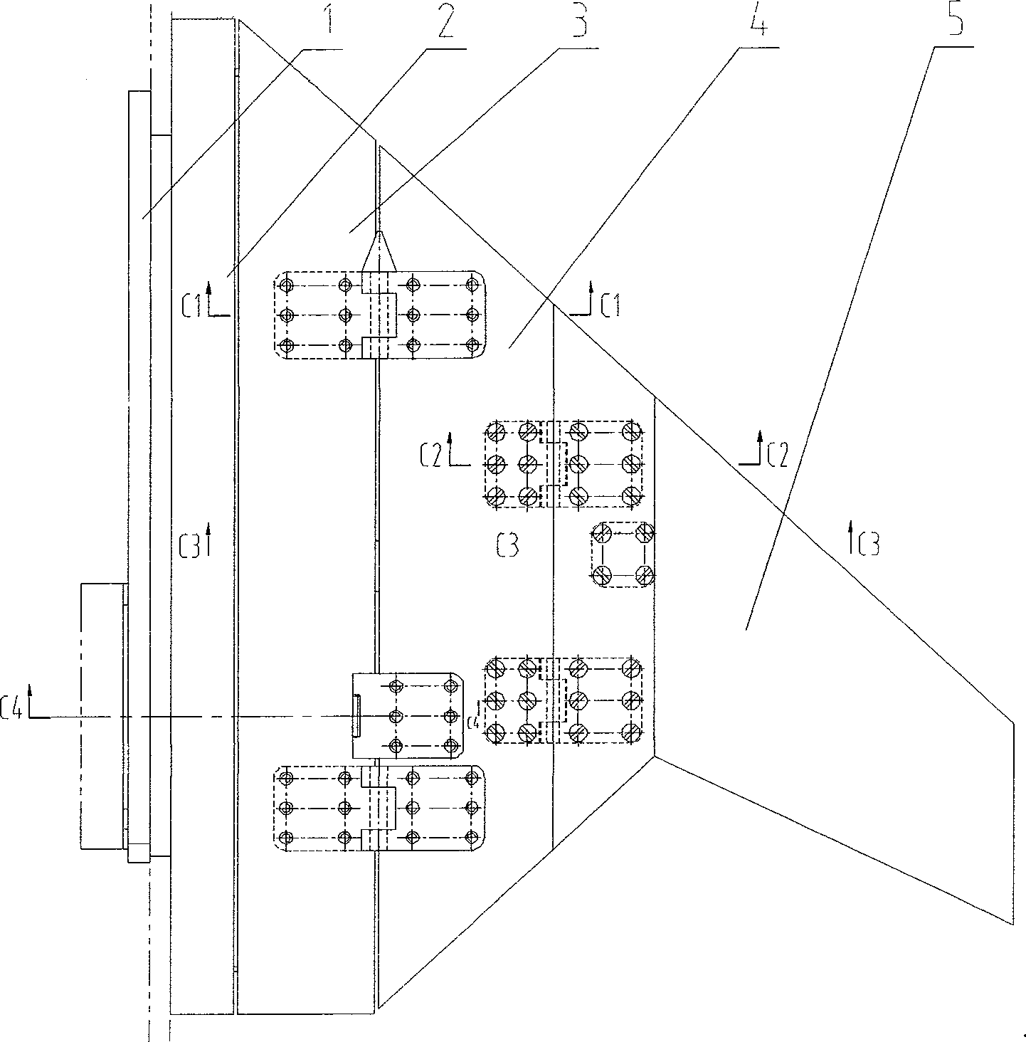
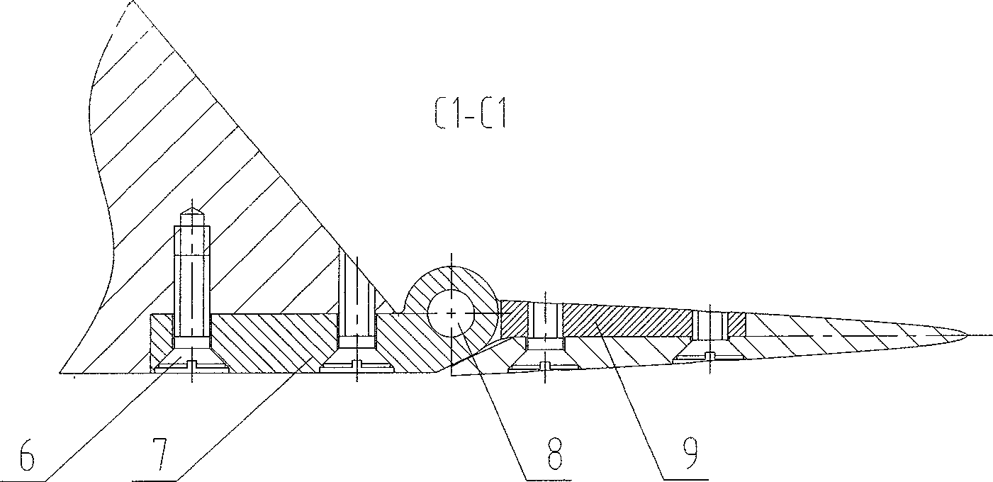
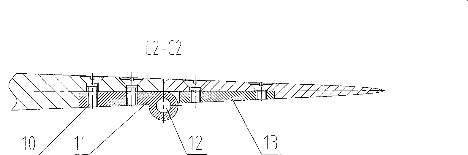
[0024] Such as figure 1 , figure 2 , image 3 , Figure 4 , Figure 5 The wind tunnel model shown is a schematic diagram of the overall structure of the folded deformed wing half model.

[0025] A wind tunnel model for folding and deforming a wing, including a fuselage [3], an inner wing [4], and an outer wing [5]. The folding and deforming mechanism is divided into an active mechanism and a driven mechanism. [4], outer wing [5], connecting rod, and hinge shaft are designed to couple the driving mechanism and the driven mechanism together, and the inner wing [4] and the fuselage [3] and the inner wing [4] and the outer wing [5] ] are provided with two connecting hinge axes parallel to each other and in the same direction as the longitudinal axis of the fuselage [3], the connecting hinge axes of the inner wing [4] and the fuselage [3] are fixed axes [8], and The connecting hinge shaft between the wing [4] and the outer wing [5] is the driven shaft [12]. The active mechani...

Embodiment 2

[0032] Such as Figure 6 , Figure 7 , Figure 8 , Figure 9 The wind tunnel model shown is a schematic diagram of the overall shape structure of the folded deformed wing.

[0033] A wind tunnel model for folding and deforming a wing, including a fuselage [3], an inner wing [4], and an outer wing [5]. The folding and deforming mechanism is divided into an active mechanism and a driven mechanism. [4], outer wing [5], connecting rod, and hinge shaft are designed to couple the driving mechanism and the driven mechanism together, and the inner wing [4] and the fuselage [3] and the inner wing [4] and the outer wing [5] ] are provided with two connecting hinge axes parallel to each other and in the same direction as the longitudinal axis of the fuselage [3], the connecting hinge axes of the inner wing [4] and the fuselage [3] are fixed axes [8], and The connecting hinge shaft between the wing [4] and the outer wing [5] is the driven shaft [12]. The active mechanism drives the in...


PUM


Abstract

The invention relates to a wind tunnel model folding deformation wing which is mainly used for measuring the pneumatic force of deformable aircraft in the wind tunnel dynamic test; traditional whole wing is divided into parts: a wing body, an internal wing, an external wing and the like; the wing body, the internal wing, the external wing, a connecting rod and a hinge shaft are coupled together with a driving mechanism and a driven mechanism controlled by a precise mechanical device; two mutually parallel longitudinal hinge shafts are arranged at the joint between the internal wing and the wing body and between the internal wing and the external wing; the hinge shaft of the internal wing and the wing body is a fixed shaft; the hinge shaft of the internal wing and the external wing is a driven shaft; the driving mechanism drives the internal wing to rotate correspondingly to the fixed shaft and drives the driven mechanism at the same time, thus leading the driven shaft to rotate correspondingly to the fixed shaft; the external wing arc plane always keeps a state parallel to the horizontal plane during the deformation running process of the wing. The wing folding deformation mechanism runs smartly and stably without noise, excellently bears the pneumatic force and pneumatic moment of the model, and realizes the digital control during the folding process, with precise positioning of the folding angle.

Description

(1) Technical field [0001] The invention relates to a wind tunnel model folded and deformed wing, which is mainly used for the wind tunnel model folded and deformed wing for measuring the aerodynamic force of a deformed aircraft in a wind tunnel dynamic test. (2) Background technology [0002] It is the pursuit of aviation science and technology personnel to fly aircraft faster, higher and farther, but none of the aircraft currently in service in the world can achieve all of the above goals at the same time. Due to technical limitations, the design of traditional fixed-wing aircraft can only be compromised for different flight tasks and states. Therefore, the aircraft can only have good aerodynamic performance in a certain airspace range and a certain speed range, and the aerodynamic performance drops very sharply when flying away from the design point, which causes the aircraft model to have a single function, maneuverability and flexibility. are subject to restrictions. ...

Claims


Application Information

Patent Timeline
Patent Type & Authority Applications(China)
IPC IPC(8): B64C3/56
Inventor 李强李周复张国友刘铁中黄丹高小荣
Owner 中国航空工业空气动力研究院
Why Eureka
Try Eureka