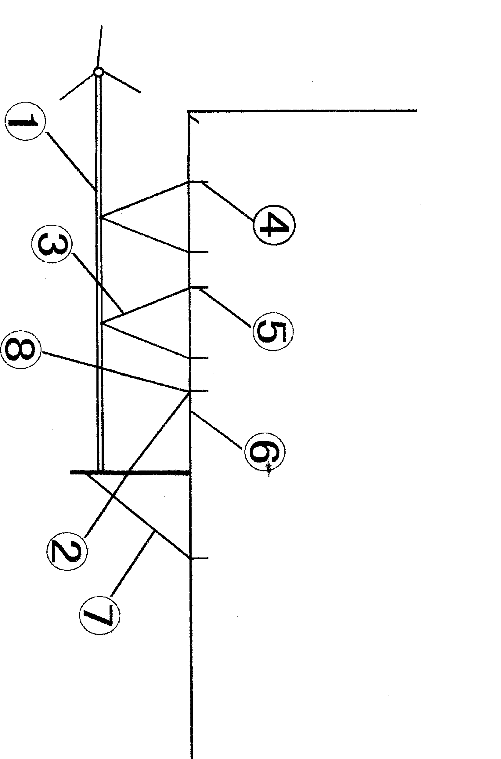
Permanently installation facilities for wind energy equipment buildings
A fixed device and wind energy technology, which is applied in the direction of wind power generation, installation/support of wind turbine configuration, mechanical equipment, etc., can solve problems such as energy depletion, increased burden on residents, and underutilization of wind energy, so as to change the energy structure and reduce consumption expenditures , the effect of reducing dependence
Inactive Publication Date: 2009-03-11
丛兴陆
View PDF0 Cites 0 Cited by
- Summary
- Abstract
- Description
- Claims
- Application Information
AI Technical Summary
Problems solved by technology
[0002] At present, the known wind energy facilities are all fixedly installed and used on the ground, and the ground space occupied by the wind energy facilities is too large. In towns with tight land, wind energy facilities cannot be installed to utilize wind energy, so that the wind energy in cities and towns cannot be rationally utilized, resulting in waste; the characteristics of wind energy are The farther the distance from the ground is, the greater the wind energy value is. The wind energy above the buildings in cities and towns is abundant, but the existing wind energy facilities cannot be used; the energy consumption in cities and towns relies on external supplies, causing energy shortages and rising energy prices, which increase the burden on residents. The energy is mainly based on conventional non-renewable mineral energy, resulting in energy depletion and environmental degradation. However, the current wind energy facilities are becoming large-scale, and the technology of large-scale wind energy facilities is not perfect, resulting in the bottom of wind energy utilization.
Method used
View moreImage
Smart ImageViewing Examples
Examples
Embodiment Construction
[0009] 在图中先在非承重垂直墙面(6)处钻孔(4),钻孔(4)深度不能超过非承重垂直墙面(6)的厚度,在钻孔(4)内植入膨胀螺栓(5),把水平面固定支架(3)与垂直面承重固定托盘支架(7)固定在膨胀螺栓(5)上,再把垂直面承重固定托盘(2)固定在垂直面承重固定支架(7)上把风能设施(1)固定安装在水平面固定支架(3)与垂直面承重固定托盘(2)上,最后把防水胶浇注在钻空密封处(8)防止雨水侵蚀墙体。
Login to View More PUM
 Abstract
The invention relates to a fixing and mounting device for a wind energy facility. The fixing and mounting device can fix the wind energy facility above a building, so that the wind energy facility can work efficiently above the building.
Description
Technical field [0001] 本发明属于风能设施附属设施。 Background technique [0002] 目前,公知的风能设施均是在地面固定安装使用,而风能设施占用的地面空间交大,在土地紧张的城镇无法安装风能设施利用风能,使城镇的风能无法合理利用,造成浪费;风能的特点是距离地面越远风能值越大,城镇楼房上方的风能很丰富,但现有风能设施却无法利用;城镇的能源消耗靠外来补给,造成能源紧张,能源涨价,使居民负担加重,而目前的能源又以常规不可再生矿物能源为主,造成能源枯竭,环境恶化,而目前的风能设施走向大型化,大型化的风能设施技术不完美,造成风能利用底下。 Contents of the invention [0003] 为了克服目前风能设施在安装使用上的弊端,合理有效的广泛使用清洁的风能。 [0004] 本发明所设计的技术方案是,把风能设施固定安装城镇楼房上,使风能设施不占用城镇有限的地面空间,合理利用城镇楼房上方空间蕴藏的丰富风能。 [0005] 本发明简单易行,在楼房顶层的非受力垂直墙面钻孔,在钻好的墙面孔里植入膨胀螺栓,再把钢铁支架固定在膨胀螺栓上,然后再把风能设施固定安装在钢铁支架上,使风能设施能够合理利用城镇楼房上方的风能。 [0006] 本发明的有益效果是,能使风能设施在地面空间有限的城镇安装使用,使风能设施合理利用城镇楼房上方丰富的风能,改变目前现有的能源结构,减轻对常规能源的依赖,减轻居民能源 expenditures. 本发明只能对中小型风能设施有效。 Description of drawings [0007] 下面是结合风能设施楼房固定安装支架水平视图和实例对本发明的进一步说明。 [0008] 图中,1.风能设施,2.垂直面承重固定托盘,3,水平面固定支架,4.墙壁钻孔,5.膨胀螺栓,6.非承重垂直墙面,7.垂直面承重固定托盘支架,8.钻孔密封处。 detailed description [0009] 在图中先在非承重垂直墙面(6)处钻孔(4),钻孔(4)深度不能超过非承重垂直墙面(6)的厚度,在钻孔(4)内植入膨胀螺栓(5),把水平面固定支架(3)与垂直面承重固定托盘支架(7)固定在膨胀螺栓(5)上,再把垂直面承重固定托盘(2)固定在垂直面承重固定...
Claims
Login to View More Application Information
Patent Timeline
 IPC IPC(8): F03D1/00F03D11/04F03D13/20
CPCY02E10/728Y02B10/30Y02E10/72
Inventor 丛兴陆
Owner 丛兴陆
Features
- R&D
- Intellectual Property
- Life Sciences
- Materials
- Tech Scout
- Unparalleled Data Quality
- Higher Quality Content
- 60% Fewer Hallucinations
Learn More Browse by: Latest US Patents, China's latest patents, Technical Efficacy Thesaurus, Application Domain, Technology Topic, Popular Technical Reports.
© 2025 PatSnap. All rights reserved.Legal|Privacy policy|Modern Slavery Act Transparency Statement|Sitemap|About US| Contact US: help@patsnap.com

