Supercharge Your Innovation With Domain-Expert AI Agents!

Charging apparatus

A technology of charging device and ventilation device, applied in the direction of circuit device, battery circuit device, circuit, etc., can solve the problem of cleaning or replacing, blocking the filter, etc.

Inactive Publication Date: 2009-03-11
ROBERT BOSCH GMBH
View PDF0 Cites 0 Cited by
  • Summary
  • Abstract
  • Description
  • Claims
  • Application Information

AI Technical Summary

Problems solved by technology

The disadvantage is that, over time, pollution particles or dust particles clog the fine filter and must be cleaned or replaced
In addition, the fine filter has the disadvantage that it is very thin and soft

Method used


Image

  • Charging apparatus
  • Charging apparatus
  • Charging apparatus

Examples


Embodiment Construction

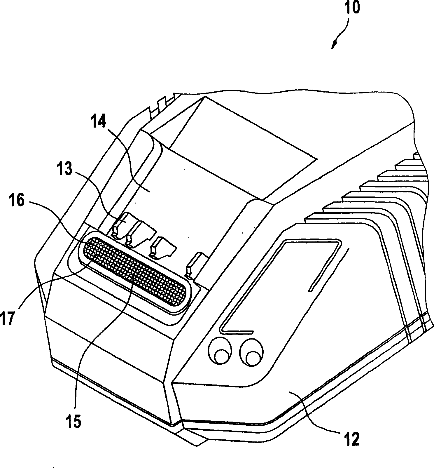
[0016] figure 1 An exemplary embodiment of a charging device 10 according to the invention is shown schematically. The charging device 10 is suitable, for example, for charging a replaceable battery pack of an electronic tool. The charging device 10 has a housing 12 which may be integral or composed of several parts, for example may consist of a lower housing cover or an upper housing cover (not shown). The housing has an insertion pocket 14 for accommodating a battery pack (not shown). In the region of the insertion pocket 14 there are contact elements 13 for electrically contacting the battery pack with the charging device 10 .

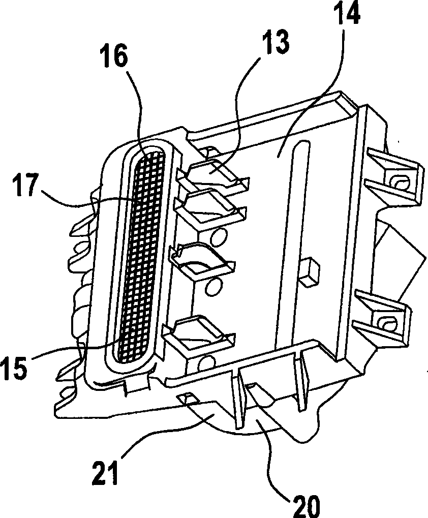
[0017] Such as figure 2 As can be seen from the enlarged view of FIG. 1 , inside the charging device 10 below the insertion box 14 , the ventilation device 20 is arranged in the housing 21 of the ventilation device. Through the air inlet hole 15 , air enters from the outside into the interior of the charging device 10 . Air is blown out via ai...


PUM


Abstract

Charging apparatus comprises a housing (12) which has at least one ventilating device (20) with a bladed fan (22), an air inlet opening (15), and a filter (16) which is arranged at the air inlet opening (15) and has a plurality of openings (17) which are at least half as large as the minimum spacing Smin of the fan blades (22).

Description

technical field [0001] The invention relates to a charging device according to the preamble of claim 1, in particular for an accumulator battery. Background technique [0002] Charging devices are known from the prior art with a ventilation device which blows, for example, cooling air into and through a coolable battery pack installed in the charging device. The opposite flow direction is also known, in which the cooling air flows into the battery pack through the inlet openings, is sucked in by the ventilation device, and passes through the battery pack. Furthermore, charging devices are known in which the electronic components of the charging device can be cooled. [0003] For this purpose, the housing of the charging device has air inlet openings and air outlet openings for sucking in air from outside the housing and discharging it again. When the air is sucked in, dust and pollution particles are also sucked in, which, depending on their size, can damage the ventilatio...

Claims


Application Information

Patent Timeline
Patent Type & Authority Applications(China)
IPC IPC(8): H01M10/44H01M10/50H05K7/20
CPCH05K7/20181H01M10/5004H02J7/0042H01M10/5067H01M10/5073H01M10/6563H01M10/6566H01M10/613Y02E60/10F04D29/4213H02J7/00
Inventor M·雷曼
Owner ROBERT BOSCH GMBH
Features
  • R&D
  • Intellectual Property
  • Life Sciences
  • Materials
  • Tech Scout
  • Unparalleled Data Quality
  • Higher Quality Content
  • 60% Fewer Hallucinations
Learn More