
Magnetic locking device

A magnetic and opening device technology, applied in the direction of building fastening devices, wing fan fastening devices, connecting components, etc., can solve the problem of no zero position, and achieve the effect of saving space

Active Publication Date: 2009-03-11
JULIUS BLUM GMBH
View PDF2 Cites 17 Cited by
  • Summary
  • Abstract
  • Description
  • Claims
  • Application Information

AI Technical Summary

Problems solved by technology

It has been found that this prior art has the disadvantage that the first part of the suction device, which is arranged on the furniture body, does not have a defined zero position when the movable furniture part is opened.
Undesirable noises may therefore be caused by the movement of the first part of the magnetic grip when the movable furniture part is closed or opened, i.e. when contact is established or broken between the two parts of the magnetic grip

Method used


Image

  • Magnetic locking device
  • Magnetic locking device
  • Magnetic locking device

Examples


Embodiment Construction

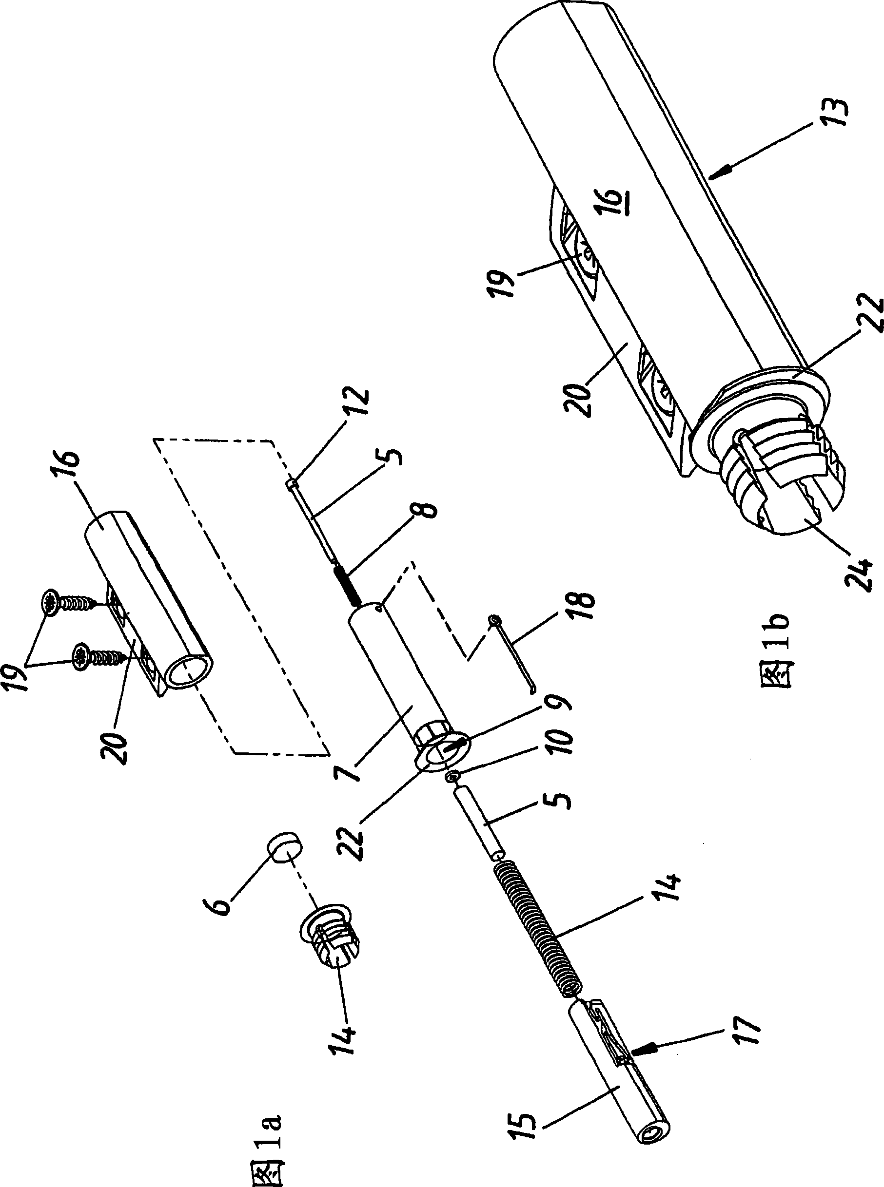
[0036] exist Figure 4 The magnetic clamping device 1 shown in has two parts 5, 6, wherein the first part 5 that is arranged on the unillustrated furniture body can protrude from its end face opening and is supported in a housing 7, In contrast, another part 6 of the magnetic gripping device is arranged in or on the movable furniture part 2 .

[0037] Here, the first part 5 of the magnetic gripping device 1 , which is arranged in the housing 7 , is loaded in the closing direction SR of the movable furniture part 2 by an energy accumulator 8 designed as a spring, wherein the energy accumulator 8 acts on the housing. 7 between a stop 11 formed in the region of the inner end opening 9 and a flange-shaped extension 12 formed on the first part 5 .

[0038] The first part 5 can pass through the front opening 9 of the housing 7 when the movable furniture part 2 is closed, due to the force of the energy accumulator 8 being smaller than the magnetic attraction force of the magnetic cl...


PUM


Abstract

Disclosed is a magnetic locking device (1) for a furniture part (2) that is movably mounted on a piece of furniture (3). The inventive locking device (1) comprises at least two pieces (5, 6), a first one (5) of which is or can be disposed on the furniture carcass (4) while the other one (6) is or can be arranged on the movable furniture part (2). Said at least two pieces (5, 6) apply a magnetic force of attraction to each other at least in the closed position (E) of the movable furniture part (2). The first piece (5) of the locking device (1), which is disposed on the furniture carcass (4), is mounted particularly in a separate housing so as to be movable in the direction of the movable furniture part (2). Furthermore, the first piece (5) of the magnetic locking device, which is assigned to the furniture carcass (4), is impinged upon by an energy store (8) that acts in the closing direction (SR) of the movable furniture part (2).

Description

technical field [0001] The invention relates to a magnetic gripping device for a piece of furniture movably supported on a piece of furniture, comprising at least two parts, wherein a first part is arranged or can be arranged on the furniture body, and a second part is arranged or can be arranged on the furniture body. Arranged on movable furniture parts, which exert a magnetic attraction on each other at least in the closed position of the movable furniture parts, wherein the first part of the clamping device arranged on the furniture body is movable toward each other, in particular in a separate housing The furniture part is mounted movably in direction. Furthermore, the invention relates to a closing and opening device for a furniture part which is movably supported on a piece of furniture, wherein the magnetic clamping device is combined with a lockable ejection device for driving the furniture part from the closed end The position moves toward the open position. Backgr...

Claims


Application Information

Patent Timeline
Patent Type & Authority Applications(China)
IPC IPC(8): E05C19/16
CPCE05C19/165E05Y2201/46Y10T292/11
Inventor A·彼得隆格
Owner JULIUS BLUM GMBH
Learn More