
Mechanical locking differential lockout mechanism

A locking mechanism, locking clutch technology, applied in mechanical equipment, differential transmission, transmission and other directions

Active Publication Date: 2009-03-11
EATON INTELLIGENT POWER LTD
View PDF4 Cites 19 Cited by
  • Summary
  • Abstract
  • Description
  • Claims
  • Application Information

AI Technical Summary

Problems solved by technology

[0006] One situation where it has been observed that conventional locking differentials do not work in a satisfactory manner occurs in vehicles equipped with a mechanical locking differential where "spin-out" of one of the drive wheels is inherent when working in the state

Method used


Image

  • Mechanical locking differential lockout mechanism
  • Mechanical locking differential lockout mechanism
  • Mechanical locking differential lockout mechanism

Examples


Embodiment Construction

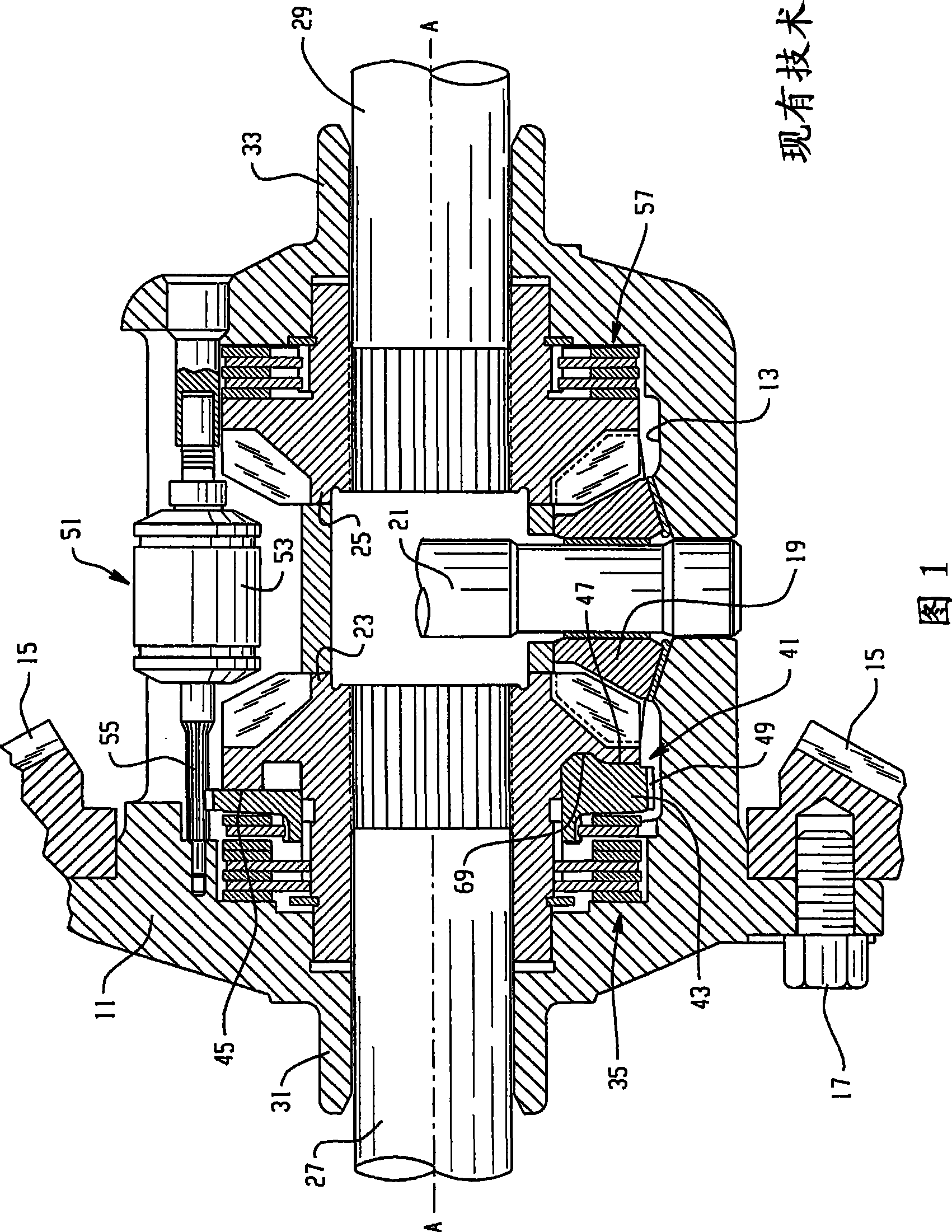
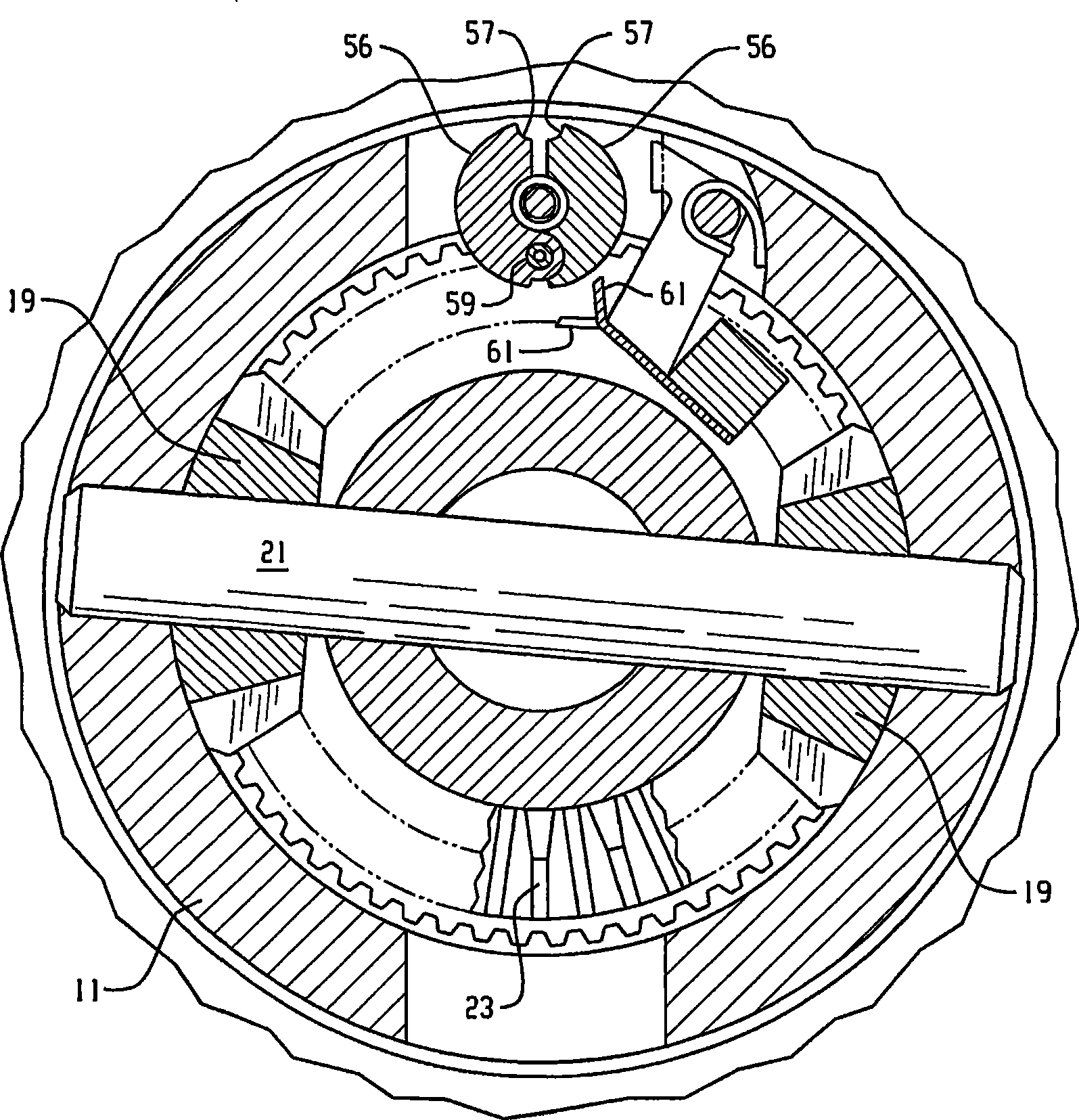
[0032] Referring now to the drawings, these drawings are not intended to limit the invention. BRIEF DESCRIPTION OF THE DRAWINGS Figure 1 is an axial cross-section of a locking differential gear mechanism in which the present invention may be advantageously employed. The general construction and operation of the locking differential shown in FIG. 1 is well known to those skilled in the art and has been depicted and described in more detail in the above incorporated patents. The differential gear mechanism shown in FIG. 1 ("Prior Art") comprises a gear housing 11 internally defining a gear cavity generally indicated at 13 . Torque is typically input to the locking differential through input gear 15 (only partially shown in FIG. 1 ). An input gear 15 (also referred to as a "ring gear") is intended to mesh with an input pinion (not shown in FIG. 1 ) that receives input drive torque from the vehicle driveline. The input gear 15 may be attached to the gear housing 11 by a pluralit...


PUM


Abstract

An improved differential gear mechanism is characterized by a lockout mechanism ( 63, 90, 129) operably associated with a flyweight mechanism ( 53 ) or latch member (119) cooperating with the flyweight mechanism (53) to block differential action of differential gear mechanism.

Description

[0001] Cross References to Related Applications [0002] This application is submitted on February 15, 2006, and the applicants are Robert J.Kyle, Keith E.Morgensai, Thomas L.Sape and Gregory L.Heatwole entitled "MechanicalLocking Differential Lockout Mechanism (mechanical locking differential lockout mechanism) )” Continuation-in-Part (CIP) of co-pending application U.S. Serial No. 11 / 354,627. technical field [0003] The present invention relates to differential gear mechanisms (differentials), and more particularly to mechanisms of the type commonly referred to as "locking differentials". More specifically, the present invention relates to mechanisms of the type also referred to as "mechanical lockers", that is, differential locking that produces a locking function in response to the operation of a mechanical device as compared to hydraulic or electromagnetic actuation. accelerator. Background technique [0004] Conventional locking differentials manufactured by the ass...

Claims


Application Information

Patent Timeline
Patent Type & Authority Applications(China)
IPC IPC(8): F16H48/30F16H48/22F16H48/08F16H48/20
CPCF16H48/22F16H48/30F16H48/34F16H2048/204F16H2048/201F16H2048/346F16H48/08F16H48/24B60K17/352
Inventor R·J·凯尔K·E·莫根赛T·L·萨佩G·L·希特沃勒
Owner EATON INTELLIGENT POWER LTD
Learn More