Polyurethane foaming agitating device

A stirring device and polyurethane technology are applied in the field of stirring devices for manual foaming of polyurethane, which can solve the problems of affecting the foaming effect, leakage of raw materials, waste, etc., and achieve the effects of novel design, reduced waste and reasonable structure

Inactive Publication Date: 2012-01-11
YANTAI ZHENGHAI HIGH TECH
View PDF0 Cites 0 Cited by
  • Summary
  • Abstract
  • Description
  • Claims
  • Application Information

AI Technical Summary

Problems solved by technology

[0002] The polyurethane foaming process is a process in which material A and material B are evenly mixed, and a chemical reaction occurs to form a foamed product. The foaming device is generally divided into an automatic foaming machine and a manual foaming device. In the high-pressure foaming machine and the low-pressure foaming machine In the foam machine, the mixing of the two raw materials is completed in the mixing head; in the manual foaming device, the mixing of the two raw materials is usually completed in the stirring device, and the commonly used stirring devices are mainly bottom-driven mixing barrels and bottomless There are two types of mixing tanks. The former is to mix the materials evenly and pour them into the foaming mold from the top of the mixing tank. The mixed materials are easy to adhere to the wall of the tank, resulting in waste; Put it in the foaming mold, when the material in the bucket is mixed evenly, lift the mixing bucket through the bracket connected to the top of the bucket, and the mixed material in the bucket will directly leak into the mold. Although it can reduce the waste of raw materials, however, The bottomless mixing tank needs to be closely matched with the bottom surface of the mold to form a container, which requires high precision in the manufacture of the mold, which will inevitably increase the processing cost of the mold, otherwise the raw materials will leak from the poor fit, resulting in improper mixing of raw materials Even, affect the foaming effect

Method used


Image

  • Polyurethane foaming agitating device
  • Polyurethane foaming agitating device
  • Polyurethane foaming agitating device

Examples


Embodiment Construction

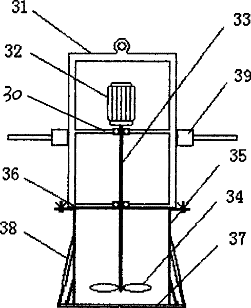
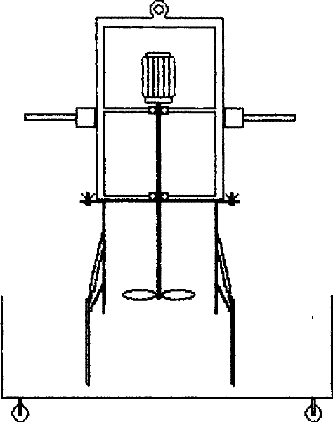
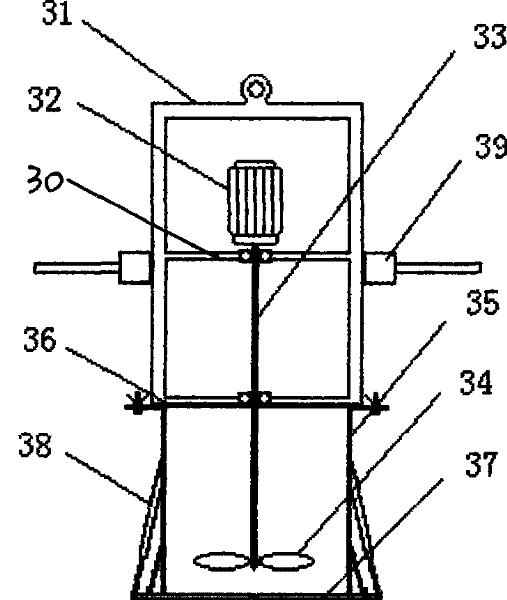
[0008] For a better understanding of the present invention, it will be further described in detail below in conjunction with the accompanying drawings and embodiments. Such as figure 1 , figure 2 As shown, the foaming device of the polyurethane foam stirring device of the present invention is composed of a frame-shaped support 31, a motor 32, a transmission shaft 33, a stirring paddle 34, a mixing bucket 35, a bucket cover 36, a bucket bottom 37 and a pneumatic or hydraulic mechanism 38, the top beam of the bracket 31 can be connected with a crane to lift the mixing bucket, the bottom beam of the bracket 31 is fixedly connected with the bucket cover 36 of the mixing bucket 35, and the bucket cover and the bucket wall are connected by bolts or buckles for easy removal , the lid is provided with a small cover that can be easily opened to facilitate feeding into the bucket; the motor 32 is fixedly installed on the beam 30 in the bracket 31, and a limit device 39 is installed on...


PUM


Abstract

The invention discloses a polyurethane foaming device, in particular to a stirring device used for manual foaming of polyurethane, which comprises a stirring barrel in which a frame bracket and a barrel cover are fixed on a bottom beam thereof, a stirring paddle which is arranged in a barrel and an electric motor which is connected with the stirring paddle by a transmission shaft and is fixedly arranged on a transverse beam in the bracket. The polyurethane foaming device is characterized in that a limiting device is arranged on the external wall of the bracket; the barrel cover of the stirring barrel is provided with a small cover which is convenient for opening and closing, and the barrel cover and the barrel wall are combined and connected in a demountable way; and the barrel bottom is formed by butt-jointing two parts which are respectively connected with hinges of the barrel wall and each hinge is respectively connected with a pneumatic mechanism or a hydraulic mechanism which is arranged on the side of the barrel wall. The device has uniform material mixing as well as convenient and thorough discharging, can effectively reduce the waste of materials and does not have special requirements to molds.

Description

1. Technical field [0001] The invention discloses a polyurethane foaming stirring device, in particular to a stirring device for manual foaming of polyurethane. 2. Background technology [0002] The polyurethane foaming process is a process in which material A and material B are evenly mixed, and a chemical reaction occurs to form a foamed product. The foaming device is generally divided into an automatic foaming machine and a manual foaming device. In the high-pressure foaming machine and the low-pressure foaming machine In the foam machine, the mixing of the two raw materials is completed in the mixing head; in the manual foaming device, the mixing of the two raw materials is usually completed in the stirring device, and the commonly used stirring devices are mainly bottom-driven mixing barrels and bottomless There are two types of mixing tanks. The former is to mix the materials evenly and pour them into the foaming mold from the top of the mixing tank. The mixed material...

Claims


Application Information

Patent Timeline
Patent Type & Authority Patents(China)
IPC IPC(8): B29B7/16B29B7/22B29K75/00
Inventor 解卫东刘夏柳春斌张应彦张伟
Owner YANTAI ZHENGHAI HIGH TECH
Why Eureka
Try Eureka