
Abrasion test method of air valve and seat ring novel abrasion test system of valve and seat ring
A wear test, valve seat ring technology, applied in the field of power machinery, can solve the problems of inconvenient data sorting and regular exploration, unfavorable progress and cycle control, accuracy and precision effects, etc., to shorten the test time and improve the reliability. , the effect of improving the accuracy
- Summary
- Abstract
- Description
- Claims
- Application Information
AI Technical Summary
Problems solved by technology
Method used
Image

Examples
Embodiment Construction
[0021] The present invention will be described in further detail below in conjunction with the accompanying drawings, but not as a limitation of the present invention.
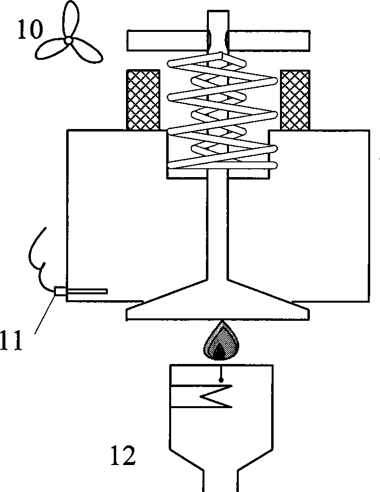
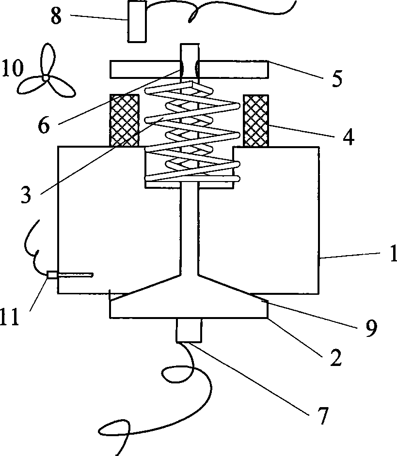
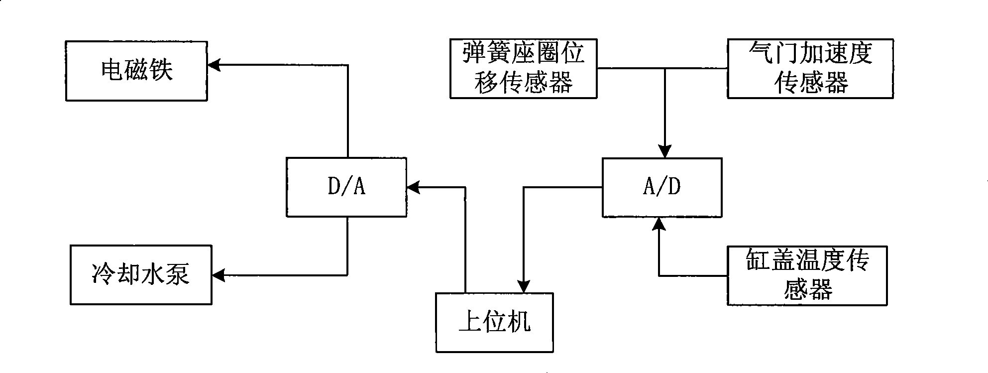
[0022] Such as figure 1 , 2 As shown, the new valve and seat ring wear test system diagram is divided into test state and calibration state state diagram. It includes: cylinder head 1, valve 2, valve spring 3, electromagnet 4, spring seat 5, valve lock clip 6, valve acceleration sensor 7, spring seat displacement sensor 8, valve seat 9, electromagnet cooling fan 10 , the cylinder head temperature sensor 11, the burner 12, the valve 2 is located on the cylinder head 1, the cylinder head temperature sensor 11 is installed on the cylinder head 1, one end of the valve spring 3 is supported on the cylinder head 1, and the other end is pressed against the spring seat ring 5 Above, the spring retainer 5 is fixed on the valve 2 with the valve lock clip 6, the electromagnet 4 is installed on the cylinder head 1, and ...
PUM
 Abstract
Description
Claims
Application Information