Supercharge Your Innovation With Domain-Expert AI Agents!

Control circuit of electric power converter

A technology of power converters and control circuits, which is applied in the direction of control/regulation systems, output power conversion devices, and conversion equipment with intermediate conversion to AC, which can solve switching cycle drift, inability to accurately control the maximum on-time of switches, The impact of the maximum on-time and other issues, to achieve the effect of stable pulse cycle

Inactive Publication Date: 2012-08-29
SYST GEN
View PDF0 Cites 0 Cited by
  • Summary
  • Abstract
  • Description
  • Claims
  • Application Information

AI Technical Summary

Problems solved by technology

However, when the high threshold signal V H , low threshold signal V L When one of the parameters of the reference voltage level drifts, the pulse width of the control signal MDC will drift, so the switching signal V PWM The switching period will drift with the
In addition, since the sawtooth wave generating circuit 10 is susceptible to interference or other factors, it cannot generate an accurate sawtooth wave signal V SAW , so with the reference voltage (V H +V L / 2) After the comparison, the pulse width of the generated control signal MDC cannot be precisely fixed, so the switching signal V PWM The maximum on-time of the switch will be affected, so that it is impossible to precisely control the switch Q 1 The maximum on-time of the power converter cannot be accurately controlled.

Method used


Image

  • Control circuit of electric power converter
  • Control circuit of electric power converter
  • Control circuit of electric power converter

Examples


Embodiment Construction

[0072] In order to enable the examiner to have a further understanding and understanding of the structural features and achieved effects of the present invention, the preferred embodiments and detailed descriptions are as follows:

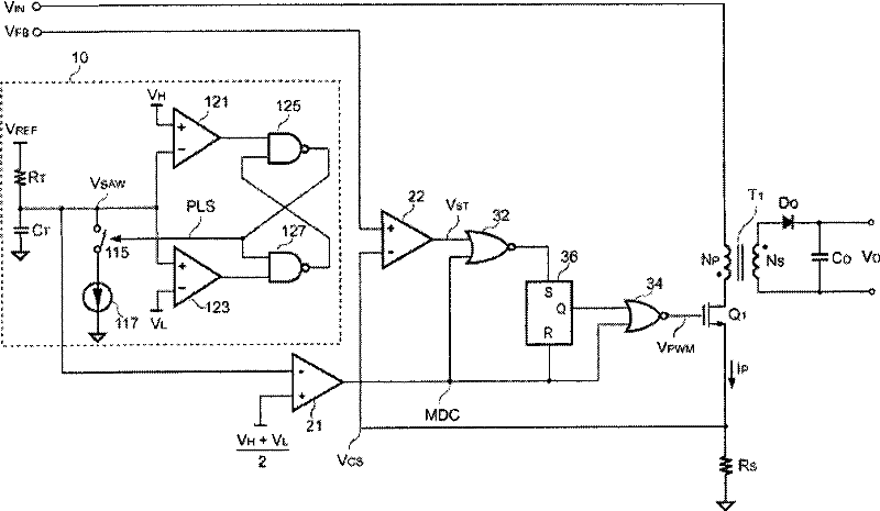
[0073] see image 3 , which is a circuit diagram of a power converter according to a preferred embodiment of the present invention. As shown in the figure, the power converter of the present invention includes a transformer T 1 , Transformer T 1 Transfer energy from the primary side to the secondary side to provide a regulated output voltage V O . Transformer T 1 The primary side and the secondary side respectively have a primary side winding N P with a secondary winding N S , primary side winding N P One end is coupled to an input voltage V IN , primary side winding N P The other end is coupled to a switch Q 1 , switch Q 1 A sensing component is connected in series, the sensing component is a resistor R in this embodiment S , switch Q ...


PUM


Abstract

The invention relates to a control circuit of a power converter. The control circuit outputs a switching signal to control a switch of the power converter and further to control the output power of the power converter and comprises an oscillator and a frequency eliminator. The oscillator generates a pulse signal and is coupled with the frequency eliminator, the frequency eliminator, is used for eliminating the frequency for the pulse signal to generate a control signal with a fixed pulse width, and the fixed pulse width controls the maximum turn-on time of a switching period of the switching signal, so as to really control the maximum turn-on time of the switch and further the maximum output power of the power converter. The invention can accurately control the maximum output power of theconverter and enhance the stability as well.

Description

technical field [0001] The present invention relates to a power converter, in particular to a control circuit of the power converter. Background technique [0002] Nowadays, due to the advancement of science and technology, many electronic products have been developed to meet the needs of the people. The functions of these electronic products are becoming more and more powerful, and bring many conveniences to the lives of the people today. Most of the current electronic devices require a power converter, which receives an input power and outputs a regulated output power according to the input power to provide the power required by the electronic device. [0003] see figure 1 , which is a circuit diagram of a prior art power converter. As shown in the figure, the prior art power converter includes a transformer T 1 , which has a primary winding NP and a secondary winding N S , primary side winding N P One end is coupled to an input voltage V IN , primary side winding N ...

Claims


Application Information

Patent Timeline
Patent Type & Authority Patents(China)
IPC IPC(8): H02M3/28H02M3/338H02M1/32
Inventor 陈振松徐乾尊江定达黄少军
Owner SYST GEN
Features
  • R&D
  • Intellectual Property
  • Life Sciences
  • Materials
  • Tech Scout
  • Unparalleled Data Quality
  • Higher Quality Content
  • 60% Fewer Hallucinations
Learn More