Polarizer manufacturing method

A manufacturing method and polarizing plate technology, applied in chemical instruments and methods, optics, polarizing elements, etc., can solve the problems of reduced irradiance, difficulty, different measurement sensitivity, etc., and achieve the effect of good bonding strength and high durability

Active Publication Date: 2012-10-17
SUMITOMO CHEM CO LTD
View PDF8 Cites 6 Cited by
  • Summary
  • Abstract
  • Description
  • Claims
  • Application Information

AI Technical Summary

Problems solved by technology

However, the power monitor has the problem that the measurement accuracy of irradiance is relatively low. The reasons are: 1) the detection wavelength of the ultraviolet sensor device is limited to a specific wavelength range, and the measurement sensitivity for each wavelength (the light absorption of each wavelength Sensitivity) is different; 2) Due to the problem of heat resistance, the irradiance of the irradiated ultraviolet light cannot be directly measured, but the reflected light of the irradiated ultraviolet light has to be measured to indirectly measure the irradiance
Due to such problems, a power monitor is applied to the manufacture of polarizing plates using UV-curable adhesives to accurately detect It is difficult to reduce the radiation intensity in the wavelength region required for the activation of the polymerization initiator in the type adhesive

Method used


Image

  • Polarizer manufacturing method
  • Polarizer manufacturing method
  • Polarizer manufacturing method

Examples


Embodiment 1

[0102] (0) Materials used for experiments

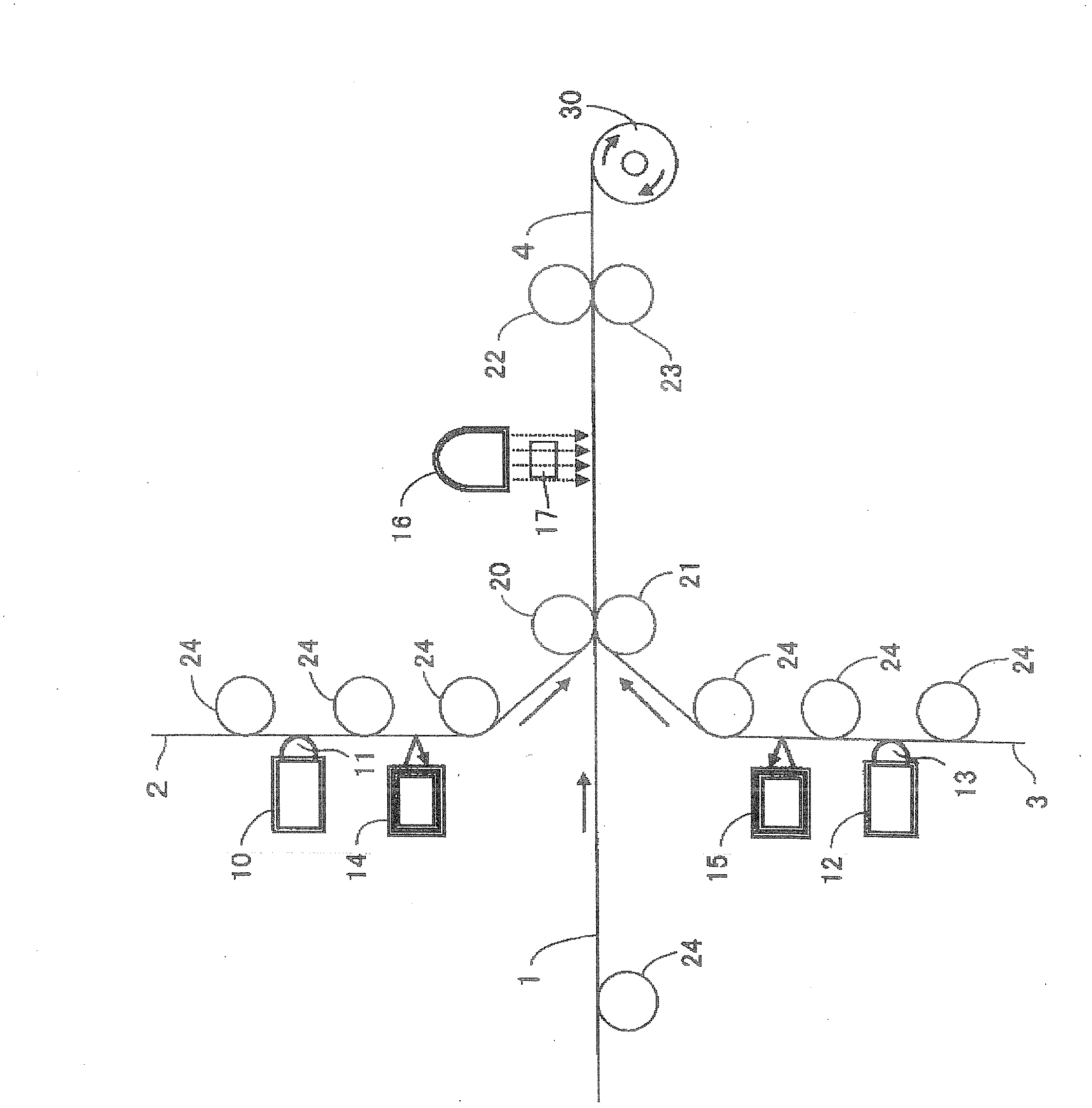
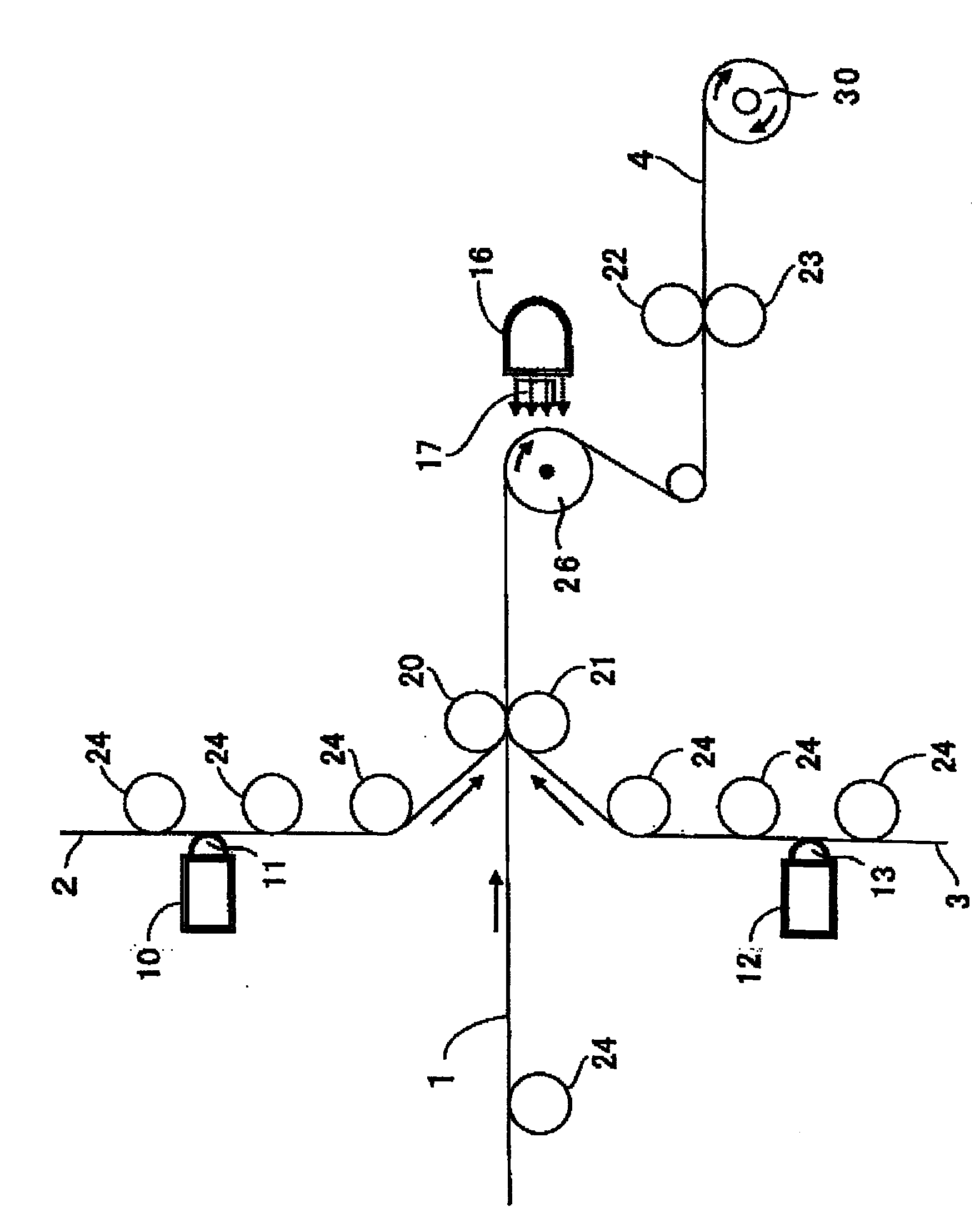
[0103]In this example, as the first optical film 2, a biaxially oriented retardation film "ZEONOR" (ゼオノア) (from Japan ゼオン (ZEON) ( Co., Ltd. acquisition]. As the second optical film 3, a propylene-based resin film having a thickness of 75 μm and a width of 1490 mm and supplied from a roll was used. The above-mentioned propylene-based resin film was obtained by melting and kneading a propylene-based resin (melting point=164° C.) at an extrusion temperature of 275° C. with a single-screw extruder, extruding it into a film form with a T-die, and making it with The cooling roll set at 20° C. was brought into close contact and solidified by cooling, and then both ends were removed with a cutter. The bonding agent used for the bonding of the polarizing film 1 and the first optical film 2, and the bonding agent used for bonding the polarizing film 1 and the second optical film 3, all contain epoxy compounds and photopolymerization initiat...

Embodiment 2

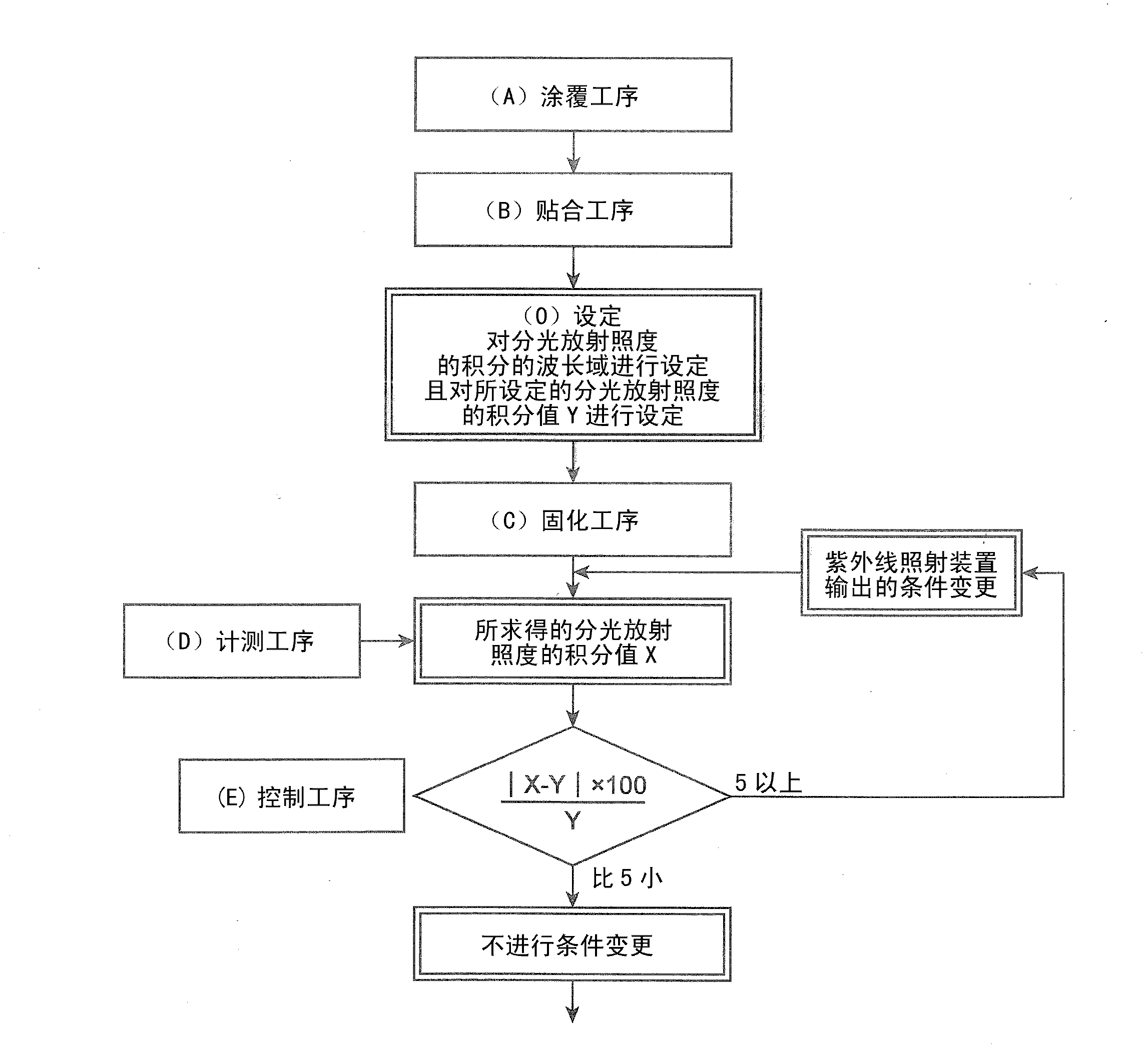
[0116] A biaxially stretched polyethylene terephthalate film with a thickness of 38 μm and a width of 1330 mm was used as the first optical film 2, and a biaxially oriented retardation film made of a cycloolefin resin with a thickness of 60 μm and a width of 1330 mm was used. ZEONOR" was used as the second optical film 3, and an epoxy-based ultraviolet-curable adhesive containing an epoxy compound and a photopolymerization initiator (absorption peak wavelength=320 nm) was used as the ultraviolet-curable adhesive. Then, except for the following points, the (A) coating process, (B) bonding process, (C) curing process, (D) measurement process and control process (E) were implemented in the same manner as in Example 1 to produce polarized light. plate.

[0117] (1) In the curing step (C), the integrated value of the spectral irradiance per one lamp in the wavelength range shown in (2) below is 200mW / cm 2 (A total of 280mJ / cm total cumulative light intensity of the 2 lamps 2 ) wh...


PUM

PropertyMeasurementUnit
thicknessaaaaaaaaaa
thicknessaaaaaaaaaa
refractive indexaaaaaaaaaa

Abstract

The invention provides a method of manufacturing a polarizer. The method comprises the steps A-E of (A) coating ultraviolet ray curing type adhesive agents on an optical film (2) made of thermoplastic resin; (B) making a polarizing film (1) made of polyving akohol overlapped on the ultraviolet ray curing type adhesive agent coating face of the optical film (2), pressurizing the optical film (2) relative to the polarizing film (1) so as to a laminated body of the polarizing film (1) and the optical film (2) attached through the ultraviolet ray curing type adhesive agents; (C) curing the adhesive agents by irradiating ultraviolet rays from an ultraviolet ray irradiating device (16); (D) obtaining the beam split irradiance integral value of ultraviolet rays comprising polymerization initiators and having absorption peak wavelengths within a specified absorption wavelength range by using irradiated ultraviolet ray beam split irradiance calculated by a beam split irradiance meter (17) of a polychromator; and (E) controlling the ultraviolet ray irradiating device (16) based on the acquired beam split irradiance integral value X and a set beam split irradiance integral value Y.

Description

technical field [0001] This invention relates to the manufacturing method of the polarizing plate used as a liquid crystal display member. Background technique [0002] A liquid crystal panel, which constitutes the core of a liquid crystal display device, is constructed by arranging polarizing plates on both sides of a liquid crystal cell. In general, a polarizing plate has a structure in which a protective film made of a transparent resin is bonded to one surface of a polarizing film made of a polyvinyl alcohol-based resin via an adhesive. In most cases, a transparent resin film is bonded to the other side of the polarizing film via an adhesive, and the transparent resin film on this side has a protective function only for the polarizing film in the same way as the protective film on the opposite side. , There is also a so-called retardation film that, in addition to the protective function, imparts a retardation in the plane and / or in the thickness direction for the purpo...

Claims


Application Information

Patent Timeline
Patent Type & Authority Applications(China)
IPC IPC(8): G02B5/30G02F1/1335
CPCB29D11/00644B32B7/12B32B27/08C09J129/04G02B5/3041G02F1/133528
Inventor 高畑弘明古川淳广岩梓清水英满矢可部公彦
Owner SUMITOMO CHEM CO LTD
Why Eureka
Try Eureka