Frame type hydraulic clamping grid die-casting machine

A die-casting machine and grid pressure technology, which is applied in the field of frame-type hydraulic locking template grid die-casting machine, can solve the problems of increasing the weight of the die-casting machine, inaccurate voltage conversion, and many welding seams, so as to achieve convenient transportation and assembly and reduce maintenance frequency , the effect of large protective area

Active Publication Date: 2013-04-24
ZIBO XINXU POWER SUPPLY TECH
View PDF12 Cites 5 Cited by
  • Summary
  • Abstract
  • Description
  • Claims
  • Application Information

AI Technical Summary

Problems solved by technology

[0002] At present, the die-casting machines used in the production of positive grids of domestic industrial lead-acid batteries generally use reversing valves. Although the cost of this reversing valve is low, the voltage conversion is inaccurate, which leads to inaccurate positioning of the mold shifting device and affects the finished grid. Specifications; the frame is generally welded by steel plates, which not only increases the weight of the die-casting machine, but also easily deforms after a long time due to the large output force of the die-casting part; only the left half of the frame has a protective cover, which cannot The personal safety of operators is well protected; the hydraulic station works at a high temperature for a long time, and it is a welded structure with the oil pipeline, with many welds, which is prone to cracks over time, causing oil leakage accidents, and is easy to burn; the mold is moving upwards Opening during the process, the mold is easy to slide when the worker takes out the grid, and it is easy to pinch people's fingers; the die-casting machine and the lead pot are separated, which is extremely inconvenient during transportation and installation

Method used


Image

  • Frame type hydraulic clamping grid die-casting machine
  • Frame type hydraulic clamping grid die-casting machine
  • Frame type hydraulic clamping grid die-casting machine

Examples


Embodiment Construction

[0018] Embodiments of the present invention are further described below in conjunction with accompanying drawings:

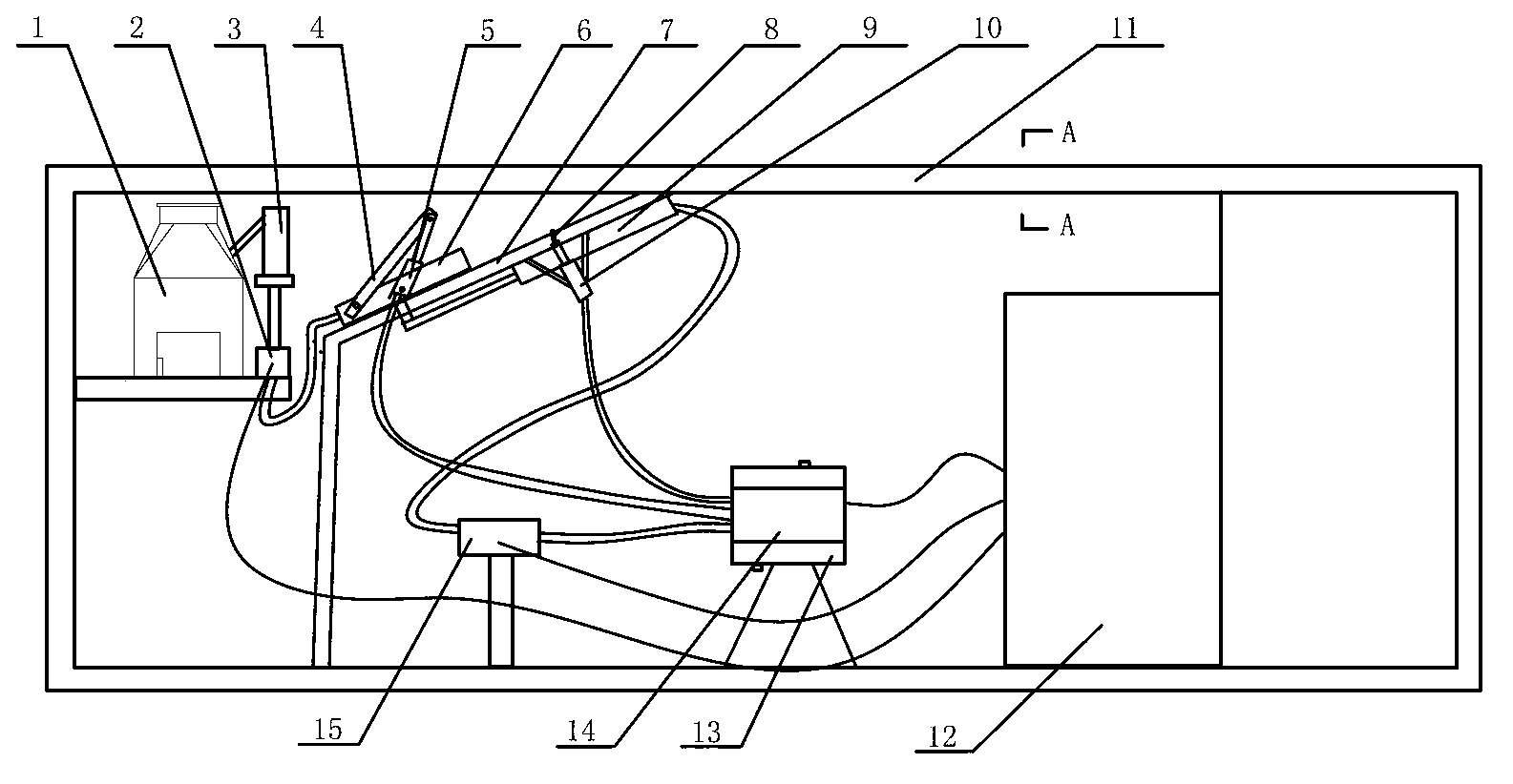
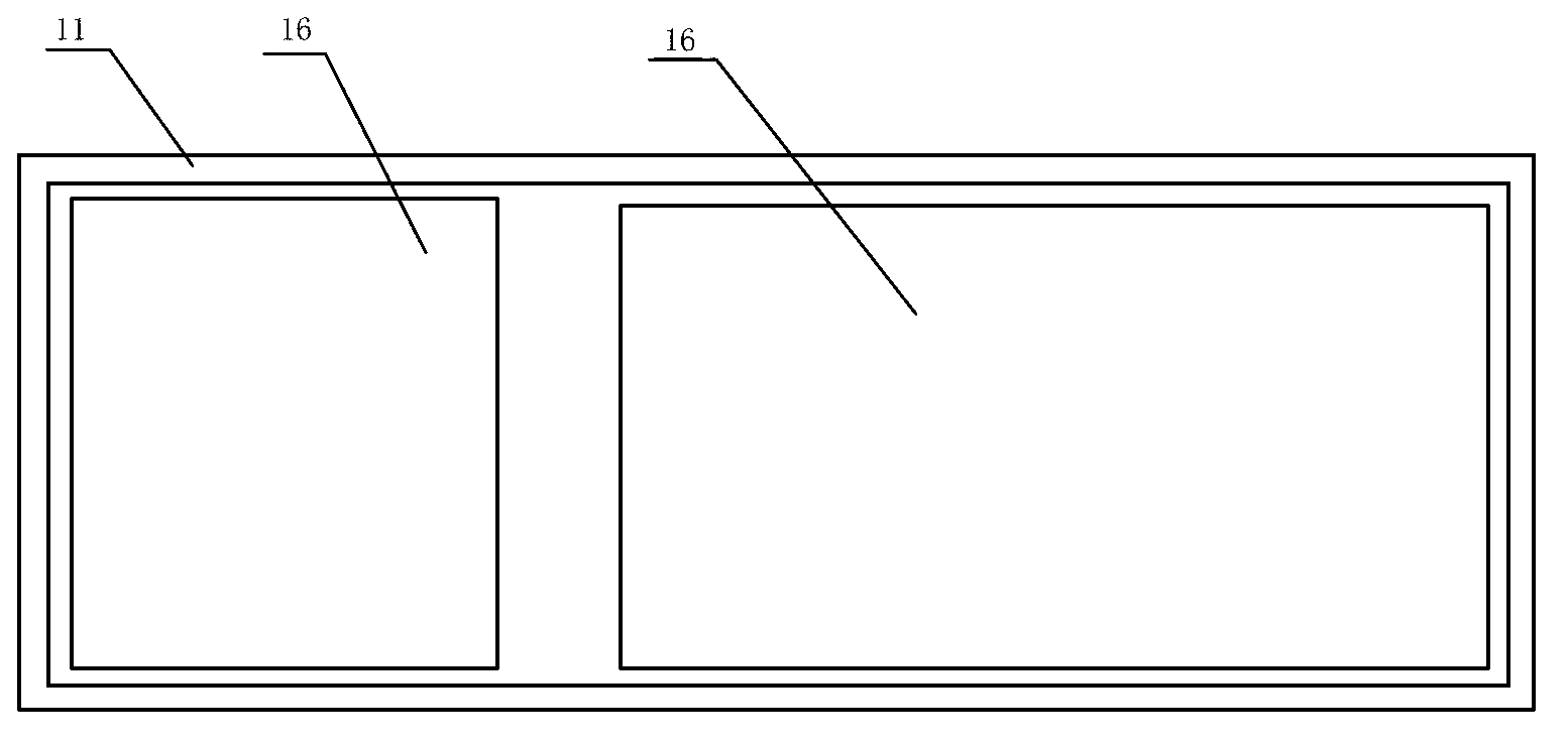
[0019] Such as Figure 1-Figure 3 As shown, the frame-type hydraulic lock formwork grid die-casting machine of the present invention includes a cuboid frame 11, a lead pot 1 is installed at the left end of the frame 11, the lead pot 1 is connected to the lead liquid pump 3, and the lead liquid pump 3 is connected to the die-casting machine. Machine 2, guide rail 7 is set on the right side of die-casting machine 2, mold 6 is installed on guide rail 7, guide rail 7, lead liquid pump 3 and die-casting machine 2 are all fixed on frame 11, proportional valve 15 is installed at the bottom of frame 11, and the mold is moved The oil cylinder 9 is connected to the hydraulic station 14 through the proportional valve 15, the mold-moving cylinder 9 is connected to the mold 6, the upper die 4 is installed on the mold 6, the clamping cylinder 5 is installed on the upper die 4...


PUM


Abstract

The invention belongs to the field of storage batteries and relates to a frame type hydraulic clamping grid die-casting machine which comprises a frame. A lead pan is mounted at the inner left end of the frame and is communicated with a lead pump, a guide rail is arranged on the right side of a die-casting machine body which is communicated with the lead pump, a die is mounted on the guide rail, the guide rail, the lead pump and the die-casting machine body are fixed on the frame, a proportional valve is mounted at the bottom of the frame, a rapid-traverse cylinder is connected with a hydraulic station through the proportional valve and is connected with the die, a clamping cylinder is mounted on an upper pressing die which is mounted on the die, the hydraulic station is mounted on the right side of the proportional valve after the clamping cylinder and the rapid-traverse cylinder are connected with the hydraulic station, and the hydraulic station, the proportional valve and the die-casting machine body are connected with an intelligent control system which is mounted on the right side of the frame. The frame type hydraulic clamping grid die-casting machine is accurate in die traverse, firm, durable, safe to operate and convenient to mount and transport.

Description

technical field [0001] The invention relates to a frame-type hydraulic locking formwork grid die-casting machine, which belongs to the field of accumulators. Background technique [0002] At present, the die-casting machines used in the production of positive grids of domestic industrial lead-acid batteries generally use reversing valves. Although the cost of this reversing valve is low, the voltage conversion is inaccurate, which leads to inaccurate positioning of the mold shifting device and affects the finished grid. Specifications; the frame is generally welded by steel plates, which not only increases the weight of the die-casting machine, but also easily deforms after a long time due to the large output force of the die-casting part; only the left half of the frame has a protective cover, which cannot The personal safety of operators is well protected; the hydraulic station works at a high temperature for a long time, and it is a welded structure with the oil pipeline,...

Claims


Application Information

Patent Timeline
Patent Type & Authority Applications(China)
IPC IPC(8): B22D17/00B22D17/32B22D17/22B22D25/04
Inventor 侯建新陈卫方安宁李宗强韦忠连康广建
Owner ZIBO XINXU POWER SUPPLY TECH
Why Eureka
Try Eureka