Optimized power amplifier and switching power supply topology

a power amplifier and switching power supply technology, applied in power management, transmission monitoring, wireless communication, etc., can solve the problems of limiting the size and effectiveness of antennas in portable wireless products, complex rf architectures of wireless products, and significant challenges for wireless communications products, so as to reduce the size and cost

Inactive Publication Date: 2013-09-10
QORVO US INC
View PDF3 Cites 6 Cited by
  • Summary
  • Abstract
  • Description
  • Claims
  • Application Information

AI Technical Summary

Benefits of technology

[0005]By using a single switching power supply instead of two separate supplies, size and cost are reduced. Further, in applications where total transmit power is limited by a Specific Absorption Rate (SAR), total transmitted RF output power may be limited. Therefore, the maximum total RF output power during the first operating mode may be equal to the maximum total RF output power during the second mode. For example, if a mobile terminal, such as a cell phone, has an SAR limit of 25 decibel milliwatts (dBm), during the first operating mode, the first RF power amplifier may transmit an RF output power of about 24 dBm, and during the second operating mode, the first RF power amplifier may transmit an RF output power of about 21 dBm and the second RF power amplifier may transmit an RF output power of about 21 dBm, for a total of about 24 dBm. Therefore, the envelope power provided by the switching power supply is the same, regardless of which operating mode is selected. As such, the single switching power supply may not be required to have any more capacity than either switching power supply in a comparable two power supply system.

Problems solved by technology

Therefore, RF architectures of wireless products may be complex.
As a result, certain performance constraints, such as Error Vector Magnitude (EVM) and other linearity constraints, may present significant challenges for wireless communications products.
Size constraints may limit the size and effectiveness of antennas in portable wireless products.

Method used


Image

  • Optimized power amplifier and switching power supply topology
  • Optimized power amplifier and switching power supply topology
  • Optimized power amplifier and switching power supply topology

Examples


Embodiment Construction

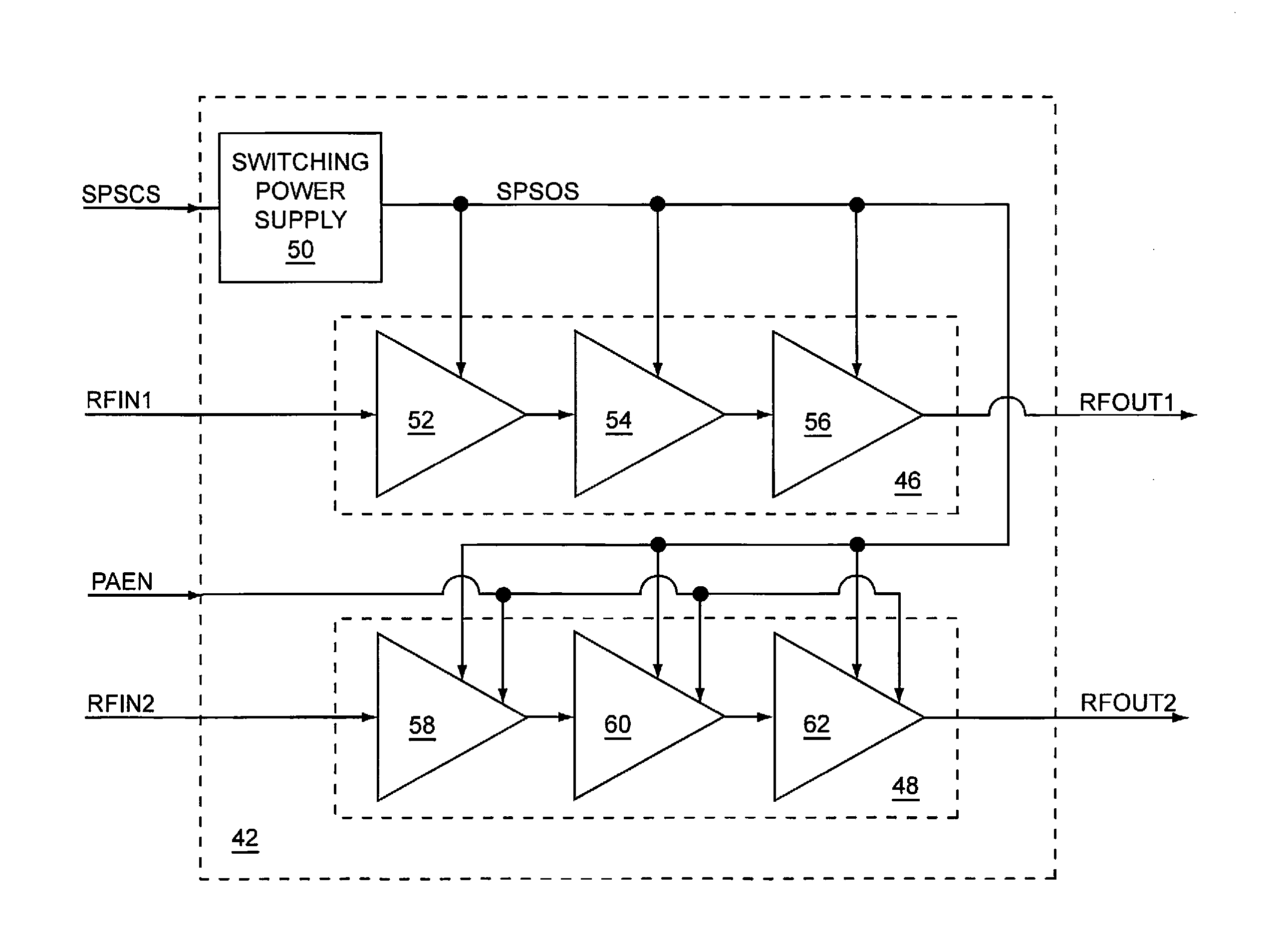
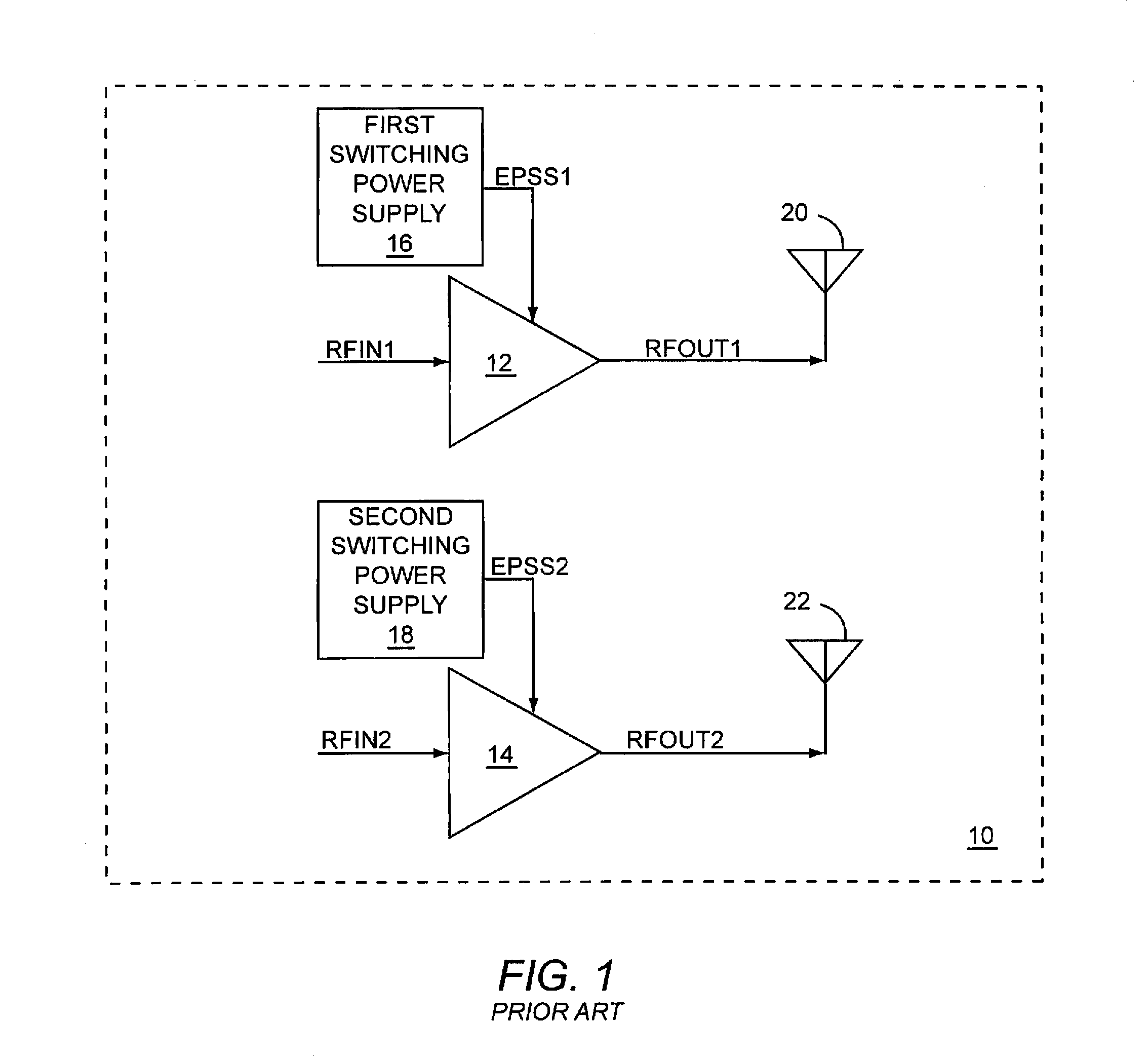
[0004]The present disclosure relates to a single switching power supply that may either provide envelope power to a first RF power amplifier during a first operating mode, or simultaneously provide envelope power to the first RF power amplifier and to a second RF power amplifier during a second operating mode. In one embodiment, the single switching power supply and the first and second RF power amplifiers may be used in a multiple-input multiple-output (MIMO) RF communications system. As such, during the first operating mode, the first RF power amplifier may transmit a first RF output signal to a first antenna, and during the second operating mode, the first RF power amplifier may transmit the first RF output signal to the first antenna and the second RF power amplifier may transmit a second RF output signal to a second antenna, which may provide diversity.

[0005]By using a single switching power supply instead of two separate supplies, size and cost are reduced. Further, in applica...


PUM


Abstract

The present disclosure relates to a single switching power supply that may either provide envelope power to a first RF power amplifier during a first operating mode, or simultaneously provide envelope power to the first RF power amplifier and to a second RF power amplifier during a second operating mode. In one embodiment, the single switching power supply and the first and second RF power amplifiers may be used in a multiple-input multiple-output (MIMO) RF communications system. As such, during the first operating mode, the first RF power amplifier may transmit a first RF output signal to a first antenna, and during the second operating mode, the first RF power amplifier may transmit the first RF output signal to the first antenna and the second RF power amplifier may transmit a second RF output signal to a second antenna, which may provide diversity.

Description

[0001]This application claims the benefit of provisional patent application Ser. No. 61 / 164,021, filed Mar. 27, 2009, the disclosure of which is hereby incorporated herein by reference in its entirety.FIELD OF THE DISCLOSURE[0002]Embodiments of the present disclosure relate to radio frequency (RF) power amplifiers and switching power supplies, both of which may be used in RF communications systems.BACKGROUND OF THE DISCLOSURE[0003]As wireless technology evolves, the number and variations of wireless communications protocols increase and may encompass multiple operating modes, including half-duplex modes and full duplex modes, multiple frequency bands, various transmit modulation schemes, various transmit power levels, and the like. As a result, wireless communications products may need to provide support for many such protocols. Therefore, RF architectures of wireless products may be complex. Evolving wireless communications protocols may be directed toward transferring as much info...

Claims


Application Information

Patent Timeline
Patent Type & Authority Patents(United States)
IPC IPC(8): H04B1/04
CPCH03F1/0238H04W52/42H04B7/06H04W52/52
Inventor KHLAT, NADIMARKISZEWSKI, ROMAN ZBIGNIEW
Owner QORVO US INC
Why Eureka
Try Eureka