

Elevator
A technology of elevators and elevator control devices, applied in the field of elevators, can solve problems such as time-consuming, time-consuming, and reduced passenger service quality
- Summary
- Abstract
- Description
- Claims
- Application Information
AI Technical Summary
Problems solved by technology
Method used
Image

Examples
no. 1 approach
[0025] First, a first embodiment of the present invention will be described.
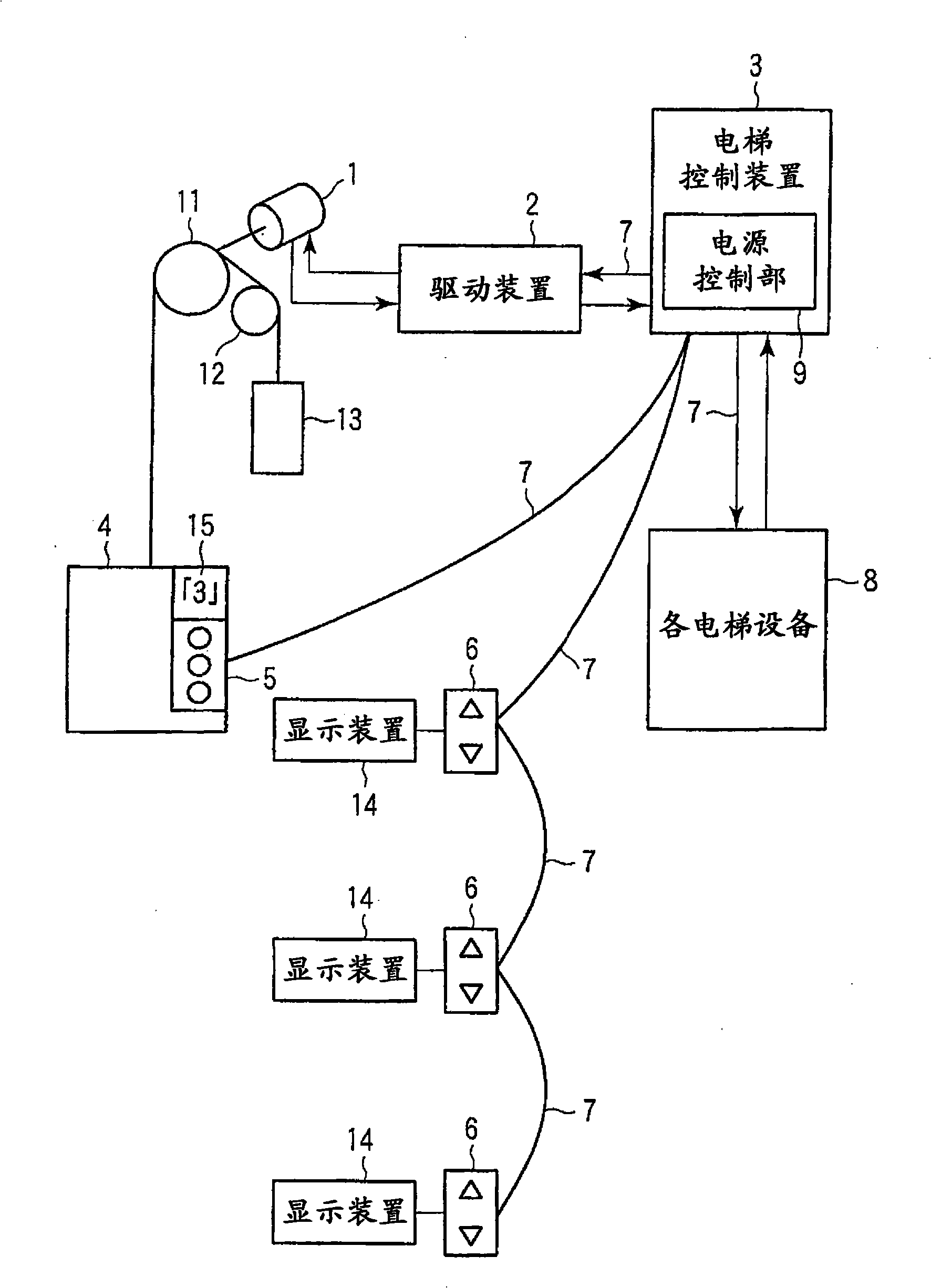
[0026] figure 1 It is a figure which shows the outline|summary of the elevator in 1st Embodiment of this invention.
[0027] Such as figure 1 As shown, the elevator in the first embodiment of the present invention has: a motor 1, a drive device 2 for driving the motor 1, an elevator control device 3, a car 4, a destination floor registration device 5, and a device for registering an elevator ride. Call registration device 6, transmission line 7 and each elevator equipment 8 at the elevator place of each floor called by place. The destination floor registration device 5 is a device for registering a destination floor in the car 4 .
[0028] The car 4 is connected to a balance weight 13 by wire ropes wound around a traction sheave 11 and a deflection sheave 12 provided on the motor shaft of the electric motor 1 . The car 4 is raised and lowered together with the counterweight 13 in vertically oppo...
no. 2 approach
[0050] Next, a second embodiment of the present invention will be described. In addition, for the structure of the elevator in this embodiment and figure 1 Explanation of parts that are the same as those shown will be omitted.
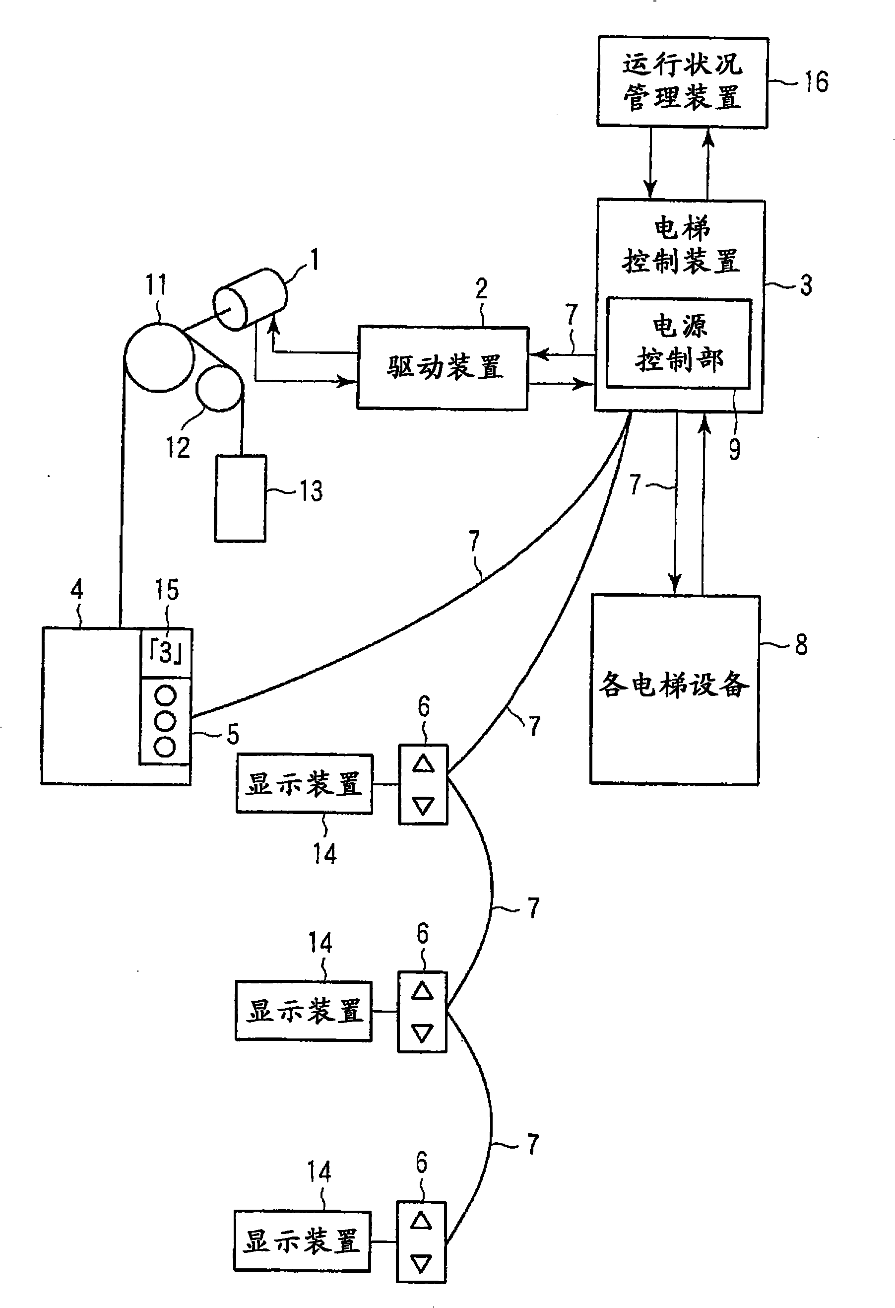
[0051] image 3 It is a figure which shows the outline|summary of the elevator in 2nd Embodiment of this invention.
[0052] Such as image 3 As shown, the elevator in the second embodiment of the present invention further has an operation status management device 16 compared with that in the first embodiment.
[0053] The operating status management device 16 counts the current time. The running status management device 16, when the timing of the timing is the start time of the time period for power-saving operation, that is, the valley time period, for example, at 23:00, it will output to the elevator control device 3 a valley state indicating that the elevator running state is a valley state. Status notification signal.
[0054] In addition, t...
no. 3 approach
[0070] Next, a third embodiment of the present invention will be described. In addition, because the structure of the elevator in this embodiment is the same as image 3 The configurations shown are substantially the same, and descriptions of the same parts are omitted.
[0071] In this embodiment, the elevator control device 3 performs group control management on the three elevators of machine A, machine B and machine C.
[0072] Next, an elevator according to Embodiment 3 of the present invention will be described.
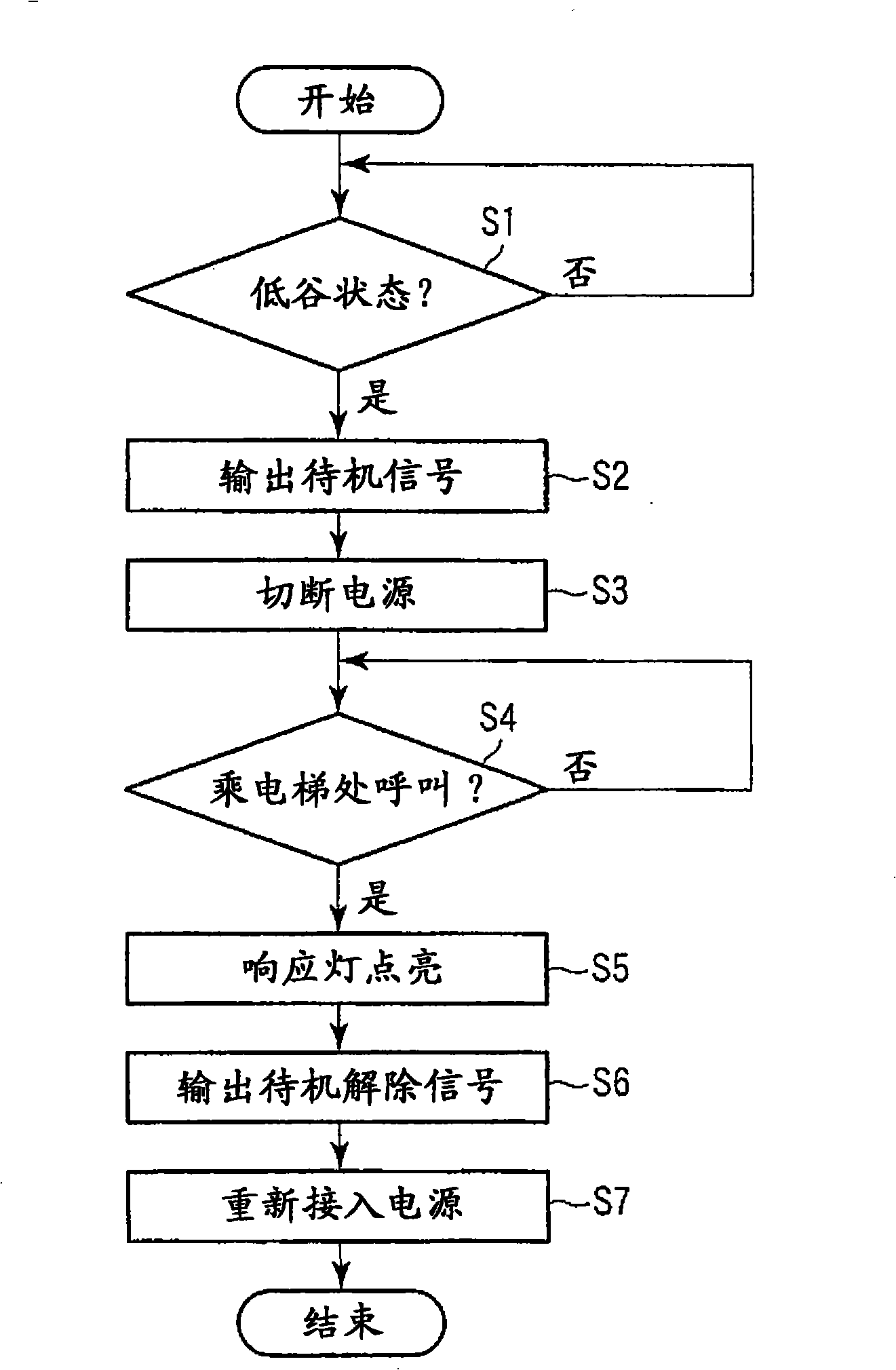
[0073] Figure 5 It is a flowchart showing an example of the processing operation of the elevator in the third embodiment of the present invention.
[0074] The elevator according to the third embodiment of the present invention performs the processing described in the first embodiment before the low-valley state notification signal from the operation status management device 16 is input to the elevator control device 3 .
[0075] The running state managemen...
PUM
 Abstract
Description
Claims
Application Information