Axial flow fan

A technology of axial flow and fan, applied in non-variable pumps, components of pumping devices for elastic fluids, machines/engines, etc., can solve the problem of not having airfoil profile, not being able to adjust the position and angle of blades, etc. problems, to achieve the effect of fewer components and lower manufacturing costs

Inactive Publication Date: 2012-08-01
加蒂责任有限公司
View PDF0 Cites 0 Cited by
  • Summary
  • Abstract
  • Description
  • Claims
  • Application Information

AI Technical Summary

Problems solved by technology

This reduces cost, however it does not allow any adjustment of the position and angle of the blades relative to the hub
In addition, the blades of existing ceiling fans are flat blades without an airfoil profile

Method used


Image

  • Axial flow fan
  • Axial flow fan
  • Axial flow fan

Examples


Embodiment Construction

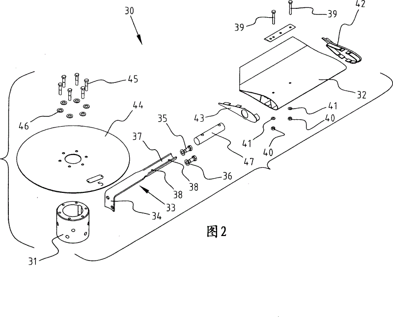
[0028] figure 2 The axial fan 30 of the present invention is shown. The axial fan 30 includes a hub 31 on which blades 32 are mounted. The L-shaped strap 33 has a short section 34 in a concave shape, and the section 34 is directly bolted to the cylindrical outer surface of the hub 31 through a bolt 35 and a washer 36. The long section 37 of the L-shaped strap 33 is partially curved and a slot-shaped opening 38 is provided. The curved part of the long section 37 is inserted into the hollow blade 32. It is also possible to install the long section of the L-shaped strip on the outside of the blade. The filling member 47 is also inserted into the blade 32, and then a bolt 39 is inserted, thereby connecting the L-shaped strip 33, the filling member 47 and the blade 32 together. The bolt 39 is fastened with a nut 40 and a washer 41.

[0029] The hollow blade 32 is closed by the end caps 42 and 43.

[0030] Finally, the closing plate 44 is connected to the hub 31 with bolts 45 and w...


PUM


Abstract

The invention relates to an axial flow type fan which comprises a hub and a plurality of blades that are evenly distributed on the hub, wherein, the blade are provided with a wing-shaped profiles and each blade is installed on the hub by torsades, wherein, each blade is hollow; moreover, at least part of the torsade is inserted into the blade, and at least one fastener passes through a corresponding opening in the torsade and reaches an opposite blade surface from the blade surface, wherein, the corresponding opening in the torsade is a narrow groove, therefore, the inclination angle of the blade can be adjusted by rotating blades relative to the torsades and along the axial lines of the blades.

Description

Technical field [0001] The invention relates to an axial flow fan, which comprises a hub and a plurality of blades evenly distributed and arranged on the hub, wherein the blades have an airfoil section. Such blades typically have a diameter of 5 meters. In order to guide the air flow, such a fan is located in a ring which preferably has a bell-shaped inlet. Background technique [0002] This kind of fan is well known and the market competition is fierce. Even a small reduction in cost can increase market share. [0003] This well-known fan has very many parts, and some of these parts are expensive to manufacture. [0004] figure 1 An exploded view of a fan in the prior art is shown. This fan includes a hub 1 on which a mounting plate 2 is mounted. The connection between the mounting plate 2 and the hub 1 is realized by six bolts 3, washers 4 and sleeves 5. Each blade 6 with an airfoil profile is mounted on the mounting plate 2. For this connection, the cast metal block 7 is bo...

Claims


Application Information

Patent Timeline
Patent Type & Authority Patents(China)
IPC IPC(8): F04D29/38F04D29/34
Inventor H・J・B・奥特霍夫G・奇佩莱蒂H・F・范德斯佩克
Owner 加蒂责任有限公司
Why Eureka
Try Eureka