Ring rolling mill and ring rolling method

A ring rolling mill, one-party technology, applied in the direction of metal rolling, metal rolling, etc., can solve the problems of inability to differentiate and incomprehensible differences, and achieve the effect of processing and high-efficiency processing

Active Publication Date: 2009-04-15
MITSUBISHI MATERIALS CORP
View PDF1 Cites 8 Cited by
  • Summary
  • Abstract
  • Description
  • Claims
  • Application Information

AI Technical Summary

Problems solved by technology

[0004] However, in the above-mentioned conventional ring rolling mill, the main roll and the mandrel are supported in such a manner that the rotation axes of the main roll and the mandrel are relatively close to or far away from each other that they are kept approximately parallel to each other, so that the main roll and the mandrel can be applied The pressing force applied to the peripheral portion of the annular body produces a difference between the respective circumferential positions on the peripheral portion, but cannot produce a difference between the respective thickness direction positions
That is, it is impossible to cause the above-mentioned pressing force to produce a local difference on the peripheral portion of the annular body.

Method used


Image

  • Ring rolling mill and ring rolling method
  • Ring rolling mill and ring rolling method
  • Ring rolling mill and ring rolling method

Examples


no. 1 approach

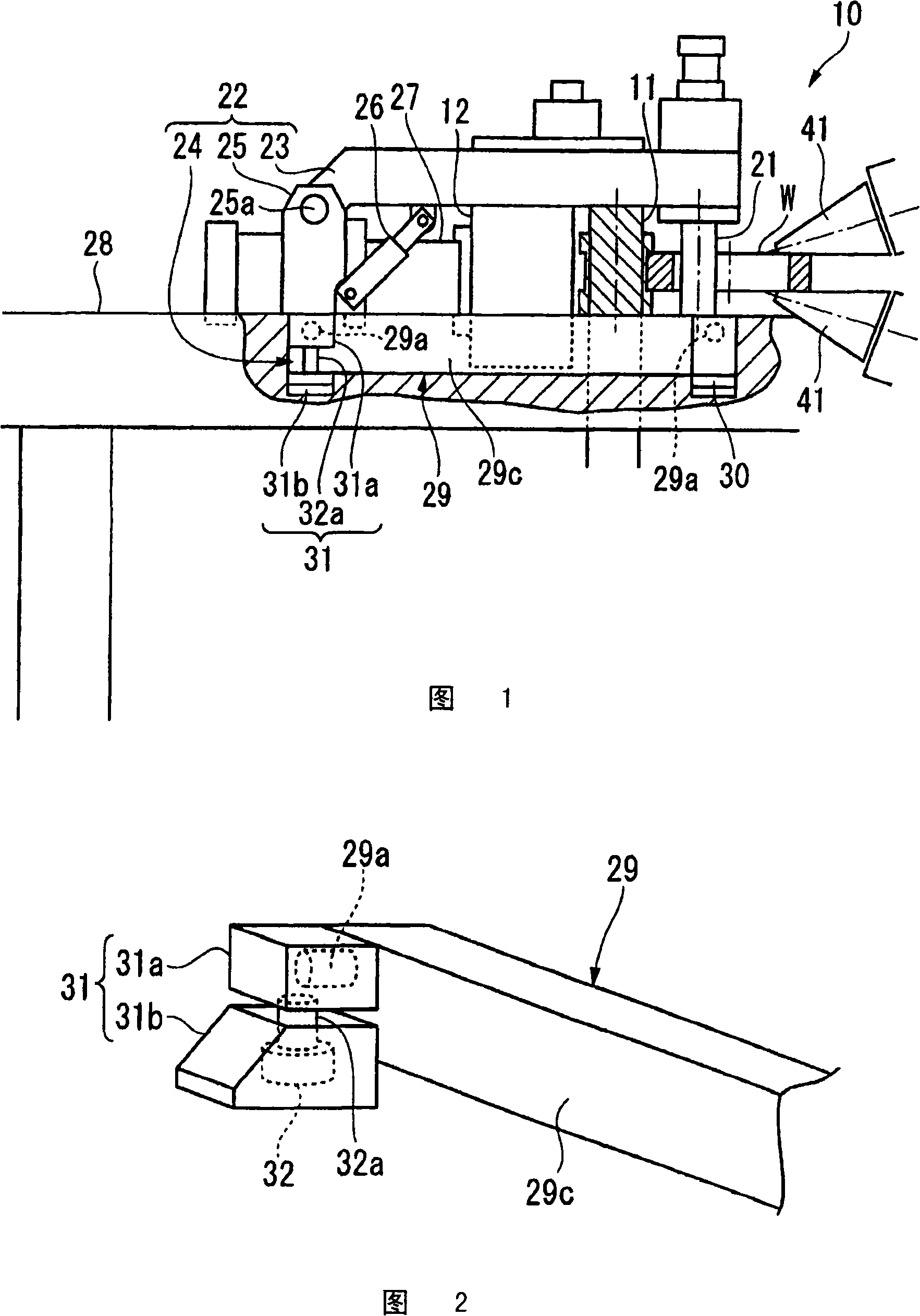
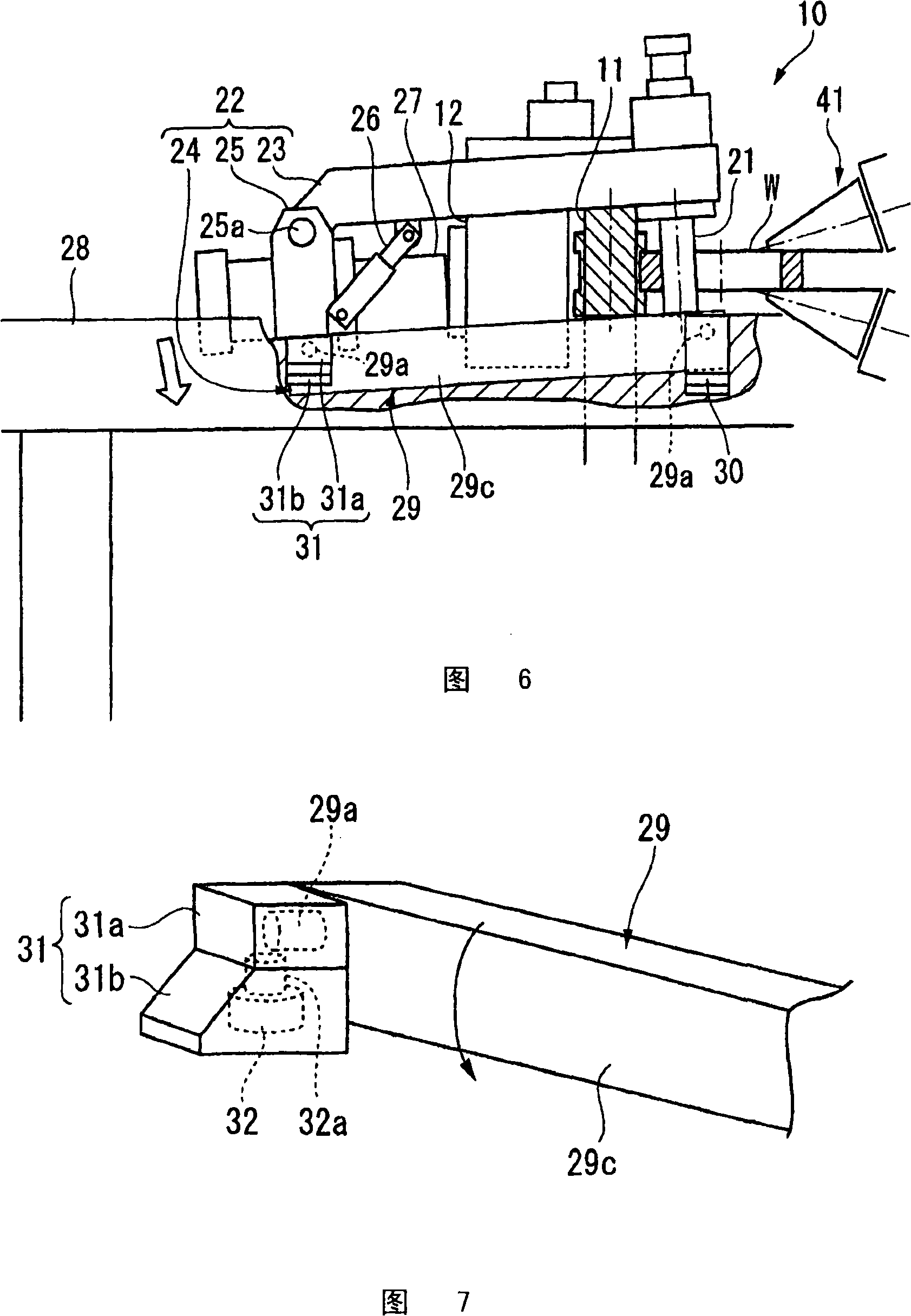
[0082] First, referring to FIGS. 1 to 10C , a first embodiment of the present invention will be described as follows. As shown in FIG. 1 , a ring rolling mill 10 according to this embodiment has a main roll 11 and a mandrel 21 which are provided so as to be close to or apart from each other. And, in a state where the peripheral portion of the annular body W is clamped in its radial direction between the outer peripheral surface of the main roll 11 that is rotationally driven about its axis and the outer peripheral surface of the mandrel 21 that is rotatable about its axis, While rotating the annular body W in the circumferential direction, the above-mentioned peripheral portion is radially rolled.

[0083] Also, the annular body W is formed by blank forging a molten ingot and then forming a through hole in the ingot.

[0084] At a position opposite to the main roll 11 and the mandrel 21 across the axis of the annular body W, a pair of axial rollers 41 sandwiching the annular ...

no. 2 approach

[0112] Below, side reference Figure 11A ~ Figure 15 A second embodiment of the present invention will be described as follows. In addition, in the following description, differences from the above-mentioned first embodiment will be mainly described, and the description of other points will be omitted as the same configuration as the above-mentioned first embodiment.

[0113] In the above-mentioned first embodiment, the mandrel 21 is tilted by rotating the entire movable frame 22 vertically and vertically, but in the ring rolling mill 110 of this embodiment, only the upper frame 23 (hereinafter referred to as the upper side frame 123) in parallel in the horizontal direction to tilt the mandrel 21, this point is particularly different.

[0114] Such as Figure 11A As shown, the ring rolling mill 110 of this embodiment has a tilting stand 122 as the mandrel tilting support mechanism of the present invention.

[0115] The tilt frame 122 has: a pair of upper frames 123 extendin...

no. 3 approach

[0137] Next, while referring to Figure 16 ~ Figure 18 A third embodiment of the present invention will be described as follows. In addition, in the following description, differences from the above-mentioned second embodiment will be mainly described, and the description of other points will be omitted as the same configuration as the above-mentioned second embodiment.

[0138] In the ring rolling mill 210 of the present embodiment, members corresponding to the upper stands 123 (hereinafter, This is particularly different in that the mandrel 21 is tilted by extending and contracting in the horizontal direction (referred to as the upper frame 223 ).

[0139] Such as Figure 16 As shown, the ring rolling mill 210 of this embodiment has: a pair of middle stands 225 as bases respectively fixed at fixed positions on each lower stand 124; A shaft body 271 parallel to the axis line CL5 parallel to the horizontal axes CL1 and CL2 ;

[0140] Each upper frame 223 has: a fixed side ...


PUM


Abstract

A ring rolling mill comprising a main roll and a mandrel capable of moving toward and away from each other, and rolling the circumferential portion of a ring-like body in the radial direction while rotating the ring-like body along the circumferential direction under such a state that the circumferential portion of the ring-like body is held in the radial direction thereof between the outer circumferential surface of the rotary driven main roll and the outer circumferential surface of the rotatable mandrel. The rolling mill further comprises a mechanism for supporting the mandrel kept inclined from the rotary axis of the main roll such that the gap between the outer circumferential surfaces of the mandrel and the main roll on one side is difference from that on the other side when viewed in the direction along the rotary axis of the main roll.

Description

technical field [0001] The present invention relates to a ring rolling mill and a ring rolling method for radially rolling the peripheral portion of a ring body. [0002] This application is based on Japanese Patent Application No. 2006-089759, and the contents thereof are incorporated herein. Background technique [0003] For example, in the conventional ring rolling mill disclosed in Patent Document 1, the peripheral portion of the annular body is sandwiched between the outer peripheral surface of the rotationally driven main roll and the outer peripheral surface of the rotatable mandrel in the radial direction. Next, while rotating the annular body in the circumferential direction, the above-mentioned peripheral portion is radially rolled. In addition, in the conventional ring rolling mill, the peripheral portion of the annular body is radially rolled on the respective outer peripheral surfaces by making the main roll and the mandrel relatively close to or away from each...

Claims


Application Information

Patent Timeline
Patent Type & Authority Applications(China)
IPC IPC(8): B21B5/00B21H1/06
CPCB21B5/00B21B17/02B21H1/06
Inventor 广濑慎平石割雄二菊池弘明泷泽英男
Owner MITSUBISHI MATERIALS CORP
Why Eureka
Try Eureka