Process and equipment for welding sealing thin-wall metal tube using laser technique

A welding sealing and laser technology technology, applied in laser welding equipment, metal processing equipment, welding equipment and other directions, can solve the problems of unreachable impact resistance, unsatisfactory welding quality and yield, and reducing the mechanical strength of metal pipes.

Active Publication Date: 2011-03-16
BEIJING ZHIBO BIO MEDICAL TECH
View PDF0 Cites 2 Cited by
  • Summary
  • Abstract
  • Description
  • Claims
  • Application Information

AI Technical Summary

Problems solved by technology

There are many methods for sealing thin-walled metal pipes. Most of them use mechanical methods to flatten the welding end of the metal pipe to form a cone, and then use spot welding or laser welding. The problem is that it is easy to cause cracks in the metal pipe, thereby reducing the mechanical strength of the metal pipe, and it is easy to cause poor sealing, the impact resistance cannot meet the requirements of the national standard, and the welding quality and yield of the product are not ideal.

Method used


Image

  • Process and equipment for welding sealing thin-wall metal tube using laser technique
  • Process and equipment for welding sealing thin-wall metal tube using laser technique
  • Process and equipment for welding sealing thin-wall metal tube using laser technique

Examples


Embodiment 1

[0049] In this example, a titanium tube with a diameter of 0.8 mm and a wall thickness of 0.05 mm and a laser spot with a diameter of 0.8 mm are taken as an example. The specific welding and sealing process is as follows:

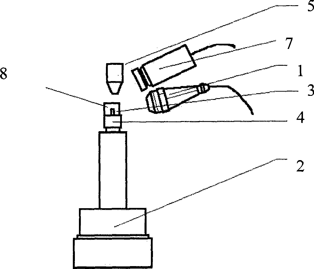
[0050] 1. Place the titanium tube 3 to be welded and sealed on the fixture 4 of the electric workbench 2;

[0051] 2. Adjust the light output energy of the laser welding machine to 2±0.1J, and the light output frequency to 6 times per second, so that it can just make the titanium tube in a molten state under the protection of an argon atmosphere, and quickly solidify on the backlight surface;

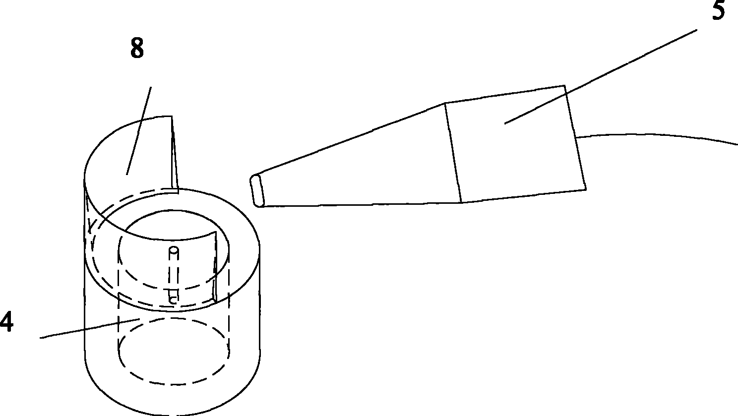
[0052] 3. Adjust the flow rate of argon to 0.2M 3 / h (cubic meter per hour), the gas pressure is adjusted to 200Kpa (kpa) by the pressure regulating valve, and the protective gas nozzle 5 is adjusted to control the flow direction, so that the molten titanium tube 3 during the whole welding process will not be oxidized or nitriding;

[0053] 4. Translate the electri...

Embodiment 2

[0062] In this example, a titanium tube with a diameter of 1.2 mm, a wall thickness of 0.05 mm and a laser spot diameter of 0.8 mm is taken as an example. The specific welding and sealing process is as follows:

[0063] 1. Adjust the light output energy of the laser welding machine to 2.2±0.1J, and the light output frequency to 8 times per second, so that it can just make the titanium tube in a molten state under the protection of an argon atmosphere, and quickly solidify on the backlight surface;

[0064] 2. Place the titanium tube 3 to be welded and sealed on the fixture 4 of the electric workbench 2;

[0065] 3. Adjust the flow rate of argon to 0.3M 3 / h, the pressure is 200Kpa, and the protective gas nozzle 5 is adjusted to control the flow direction, so that the molten titanium tube 3 will not be oxidized or nitrided during the entire welding process;

[0066] 4. Translate the electric workbench 2 so that the top welding spot of the titanium tube 3 is just at the focal p...

Embodiment 3

[0075] In this example, a titanium tube with a diameter of 1.2 mm and a wall thickness of 0.08 mm and a laser spot with a diameter of 0.8 mm are taken as an example. The specific welding and sealing process is as follows:

[0076] 1. Adjust the flow rate of argon to 0.1M 3 / h, the pressure is 200KPa, and the protective gas nozzle 5 is adjusted to control the flow direction, so that the molten titanium tube 3 will not be oxidized or nitrided during the whole welding process;

[0077] 2. Adjust the light output energy of the laser welding machine to 2.5±0.1J, and the light output frequency to 8 times per second, so that it can just make the titanium tube in a molten state under the protection of an argon atmosphere, and quickly solidify on the backlight surface;

[0078] 3. Place the titanium tube 3 to be welded and sealed on the fixture 4 of the electric workbench 2;

[0079] 4. Translate the electric workbench 2 so that the top welding spot of the titanium tube 3 is just at t...


PUM


Abstract

The invention discloses a process for welding a sealed thin-wall metal pipe by the laser technique, which comprises that the flow rate and the pressure of protective gas are set; the outlet energy and the outlet frequency of laser are set; the thin-wall metal pipe is placed in the focusing position of the laser; the thin-wall metal pipe rotates in the stepping mode, in the state of each stepping rotation positioning, the thin-wall metal pipe is welded by the laser, and is melted toward the center, depressed and solidified to form a dumb-bell-shaped column with a plurality of edges; and the thin-wall metal pipe is continuously rotated and continuously irradiated by the laser to quickly melt the top end of the thin-wall metal pipe, and forms a hemispherical sealed shell under the action of the surface tension of the molten metal, and the thin-wall metal pipe is naturally cooled down in the environment of the protective gas, and simultaneously the top end of the thin-wall metal pipe is coagulated to form the sealing state under the cooling action of the protective gas. Moreover, the invention also discloses equipment matched with the process.

Description

technical field [0001] The invention relates to a welding and sealing process and equipment for thin-walled metal pipes, more specifically, to a process and equipment for welding and sealing thin-walled metal pipes using laser technology. Background technique [0002] At present, it is a very effective technology to use thin-walled metal tubes such as titanium tubes to seal the sealed seed source. There are many methods for sealing thin-walled metal pipes. Most of them use mechanical methods to flatten the welding end of the metal pipe to form a cone, and then use spot welding or laser welding. The problem is that it is easy to cause cracks in the metal pipe, thereby reducing the mechanical strength of the metal pipe, and it is easy to cause poor sealing, the impact resistance cannot meet the requirements of the national standard, and the welding quality and yield of the product are not ideal. Contents of the invention [0003] The object of the present invention is to pr...

Claims


Application Information

Patent Timeline
Patent Type & Authority Patents(China)
IPC IPC(8): B23K26/12B23K101/06B23K26/20B23K26/08B23K26/21
Inventor 林春平孙继壮
Owner BEIJING ZHIBO BIO MEDICAL TECH
Why Eureka
Try Eureka