
Air pressure power multiplying cylinder

A double force cylinder and air cylinder technology, applied in the field of pneumatic double force cylinder, can solve the problems of large structure of force force mechanism, poor mechanical transmission effect, space limitation, etc., achieve smooth and fast movement, stable movement, and reduce air pressure power consumption Effect

Inactive Publication Date: 2009-04-22
吴焕彬
View PDF0 Cites 1 Cited by
  • Summary
  • Abstract
  • Description
  • Claims
  • Application Information

AI Technical Summary

Problems solved by technology

[0005] The technical problem to be solved by the pneumatic multiplier cylinder of the present invention is that the connecting rod set in the multiplier mechanism of the existing structure is to drive the short arm with the long arm to achieve the labor-saving effect of the lever principle, but even The rod group needs to be equipped with a long moment arm structure, which causes space restrictions. If a high force-saving effect is to be achieved, it must be equipped with multi-stage long and short moment arm conversions. This will not only result in a larger structure of the double force mechanism, but also It also causes the problems of complex structure and poor mechanical transmission effect

Method used


Image

  • Air pressure power multiplying cylinder
  • Air pressure power multiplying cylinder
  • Air pressure power multiplying cylinder

Examples


Embodiment Construction

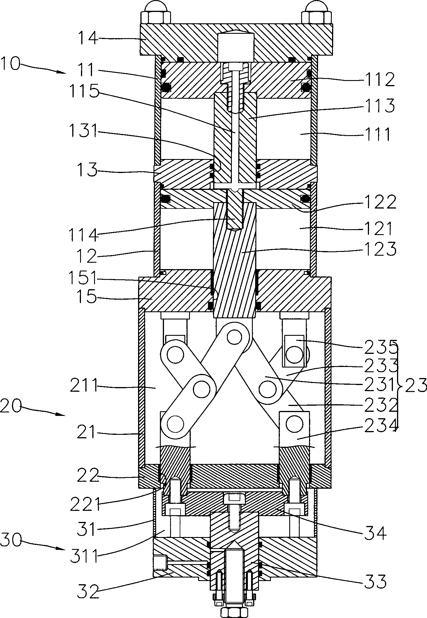
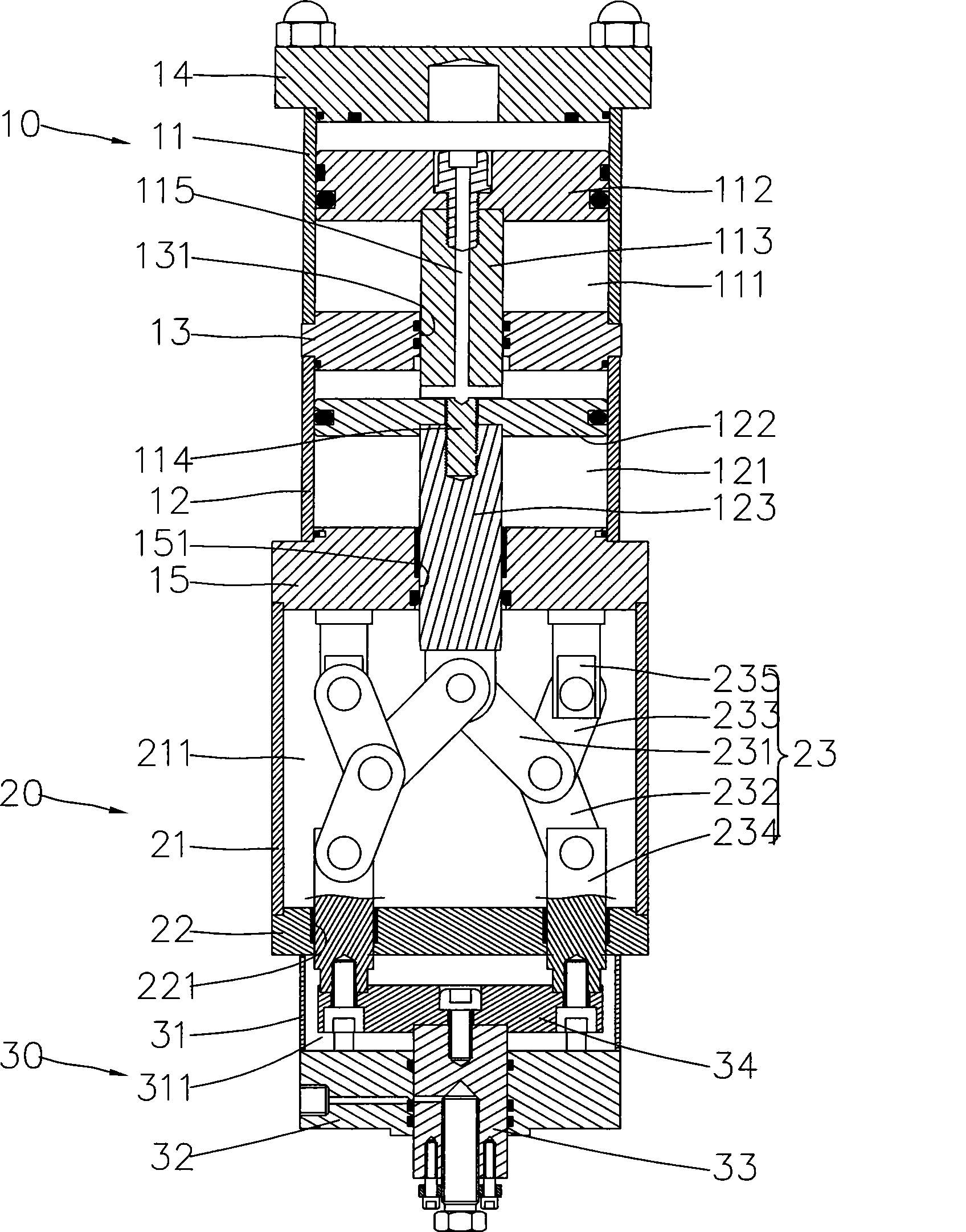
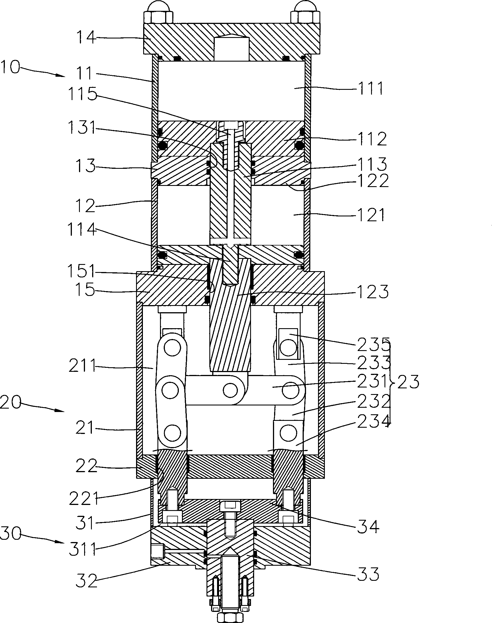
[0016] refer to figure 1 and figure 2 , the present invention includes a cylinder unit 10, a force multiplier unit 20 and an output unit 30; the force multiplier unit 20 is provided with a toggle mechanism to provide a multiplied output force. in:

[0017] The cylinder unit 10 includes a first cylinder block 11 and a second cylinder block 12 which are connected in series, and a central hole 131 is provided between the first cylinder block 11 and the second cylinder block 12. seat 13, so that an air chamber 111, 121 is formed between the two cylinder blocks 11, 12, respectively. The first cylinder 11 is equipped with a first piston 112 that can move in the air chamber 111, and the first piston 112 is screwed with a first piston rod 113 that extends through the hole 131 of the middle seat 13. . One end of the first piston rod 113 is formed with a joint portion 114 protruding into the air chamber 121 of the second cylinder 12 , and the first piston rod 113 is provided with a...


PUM


Abstract

The invention relates to a pneumatic booster cylinder. The booster cylinder comprises a high pressure air actuated cylinder unit and a booster unit connected with one end of the cylinder unit for output boosted pressure of the cylinder unit, wherein the inside of the booster unit is provided with two sets of transmission devices. Each transmission device comprises an input rod and a toggle mechanism. One end of the input rod is pivoted on the cylinder unit and the end, opposite to the cylinder unit, of the input rod is pivoted on the toggle mechanism. One end of the toggle mechanism is pivoted with a transmission bar. A power supply unit has an output shaft which is connected with the transmission bars of the transmission devices to supply a boosted force.

Description

technical field [0001] The invention relates to a pneumatic multiplier cylinder, in particular to a more stable pneumatic multiplier cylinder with better transmission effect. Background technique [0002] Please refer to Fig. 4, which is a schematic diagram of a double-force mechanism of an existing booster cylinder, which includes a booster portion 1 and a force-doubler mechanism 5; the booster portion 1 is composed of two air cylinders 2 connected in series, and in A group of piston rods 3 and pistons 4 are respectively arranged inside; the multiplier mechanism 5 has a connecting rod group 6, which forms two stages of labor-saving output by virtue of the long moment arm driving the short moment arm to achieve labor-saving effect. [0003] The described existing structure still has many disadvantages practically, because the connecting rod group 25 set in the described multiplier mechanism 20 is to drive the short moment arm with the long moment arm to achieve the labor-sav...

Claims


Application Information

Patent Timeline
Patent Type & Authority Applications(China)
IPC IPC(8): F15B15/02
Inventor 吴焕彬
Owner 吴焕彬
Learn More