Connector for coaxial cable

A coaxial cable and connector technology, applied in the direction of conductive connection, connection, two-component connection device, etc., can solve the problems of cumbersome crimping operation, and achieve the effect of easy crimping operation

Inactive Publication Date: 2009-04-22
MASPRODENKOH KK
View PDF2 Cites 1 Cited by
  • Summary
  • Abstract
  • Description
  • Claims
  • Application Information

AI Technical Summary

Problems solved by technology

The problem is that the crimping operation is cumbersome

Method used


Image

  • Connector for coaxial cable
  • Connector for coaxial cable
  • Connector for coaxial cable

Examples


no. 1 approach

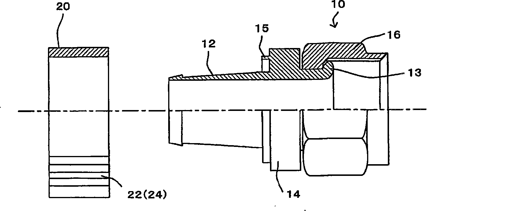
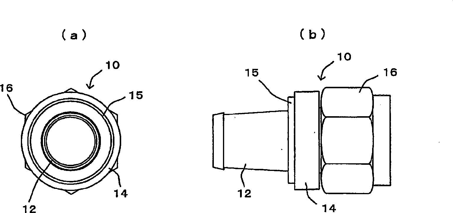
[0073] figure 1 is a partial cross-sectional view showing the composition of a coaxial cable connector (hereinafter simply referred to as a connector) according to an embodiment of the present invention. figure 2 (a) and (b) are shown figure 1 Explanatory drawing of the appearance of the connector body shown. exist figure 1 In , the part above the dot-dash line along the central axis of the connector shows the section of the connector, while the part below the dot-dash line shows the appearance of the connector. figure 2 (a) is an end view of the connector body seen from the side mounted on the coaxial cable. figure 2 (b) is a side view of the connector body.

[0074] The connector of the present invention is used to connect a coaxial cable to a connection object such as an F-type relay and an F-type antenna terminal. Such as figure 1 shown, withFigure 15 Like the conventional connectors shown in (a) to (e), the connector of the present invention includes a connec...

Embodiment approach 1

[0085] (Variation 1: see Figure 4 (a) and (b))

[0086] For example, in the above embodiments, the annular protrusion 15 suitable for fitting with the inner surface of the locking ring 20 protrudes from the flange portion 14 of the connector body 10 . However, for example, as Figure 4 As shown in (a) and (b), several protrusions 17 (three in the figure) may be arranged at the flange portion 14 of the connector body 10 to fit with the inner surface of the locking ring 20 . In this way also, the same effects as those of the above-described embodiment can be obtained. If several protrusions 17 protrude from the flange portion 14 , the size and quantity of the protrusions 17 can be appropriately set according to the size and weight of the fixing ring 20 , so as to fix the locking ring 20 .

[0087] In addition if Figure 4 As shown in (a) and (b), if the knurling is formed on the outer surface of the fitting portion 16 of the connector body 10, slippage that occurs when the ...

Embodiment approach 2

[0089] (Variation 2: see Figure 5 (a), (b) and (c))

[0090] For example, if Figure 5 (a) to (c), in the case where the connecting body 10 is provided with an annular skirt 18 from the outer peripheral edge of the flange portion 14 toward the opposite side of the fitting portion 16 to surround the end of the coaxial cable, it is possible to The inner diameter of the skirt 18 (or the outer diameter of the locking ring 20 ) is set so that the locking ring 20 can be directly fitted to the inner surface of the skirt 18 .

[0091] However in this case, as Figure 5 As shown in (a) to (c), when the crimping protrusions 20, 24 protrude from the locking ring 20, a part of the skirt 18, which is the annular protrusion protruding from the flange part 14, must be notched. , so that when the locking ring 20 is engaged with the skirt 18, the crimping protrusions 20, 24 protruding from the locking ring 20 can reach outside the ring of the skirt 18, and can be clamped with pliers or the...


PUM


Abstract

A connector for a coaxial cable has a connector body and a securing ring. The connector body has a tubular insertion section that is insertable between an insulation member around a core conductor of the coaxial cable and a woven conductor around the insulation member, a flange section that is provided around the insertion section and with which both the woven conductor of the coaxial cable and a cover member around the woven conductor come into contact when the insertion section is inserted in the coaxial cable to position the insertion section, and an annular fitting section that is provided at the insertion section, on the opposite side of the coaxial cable, and into which an object to be connected is insertable. The securing ring is used to press and fix the coaxial cable to the insertion section from the periphery of the coaxial cable after the insertion section of the connector body is inserted in the coaxial cable. The connector has a fixation section for fixing the connector body and the securing ring together.

Description

technical field [0001] The present invention relates to a coaxial cable connector which is installed at the end of a coaxial cable and connects the coaxial cable to a connection object such as an F-type relay, an F-type antenna terminal, and the like. Background technique [0002] Conventionally, this type of coaxial cable connector is known, which has a connector body 10 and a locking ring 20 . Such as Figure 15 As shown in (a), the connector body 10 includes a cylindrical insertion portion 12, a flange portion 12 and a fitting portion 16. The cylindrical insertion portion 12 can be inserted into the insulating member 6 around the core wire 4 and the braiding around the insulating member 6. Between the conductors 8, the flange portion 14 is arranged around the insertion portion 12 to position the coaxial cable, and the fitting portion 16 is rotatably arranged on the insertion portion 12 on the opposite side of the coaxial cable, and is connected to an object such as an F-t...

Claims


Application Information

Patent Timeline
Patent Type & Authority Applications(China)
IPC IPC(8): H01R24/02
CPCH01R9/0518
Inventor 杉浦敏博稻吉常之中根亲彦鸟山重光星野义朗大津正裕
Owner MASPRODENKOH KK
Why Eureka
Try Eureka