Shaft sealing structure for handle of rack lock

A shaft sealing and handle technology, which is applied in the sealing structure field of cabinet locks, can solve the problems of poor sealing of the gap between the handle shaft and the lock body, lower waterproof and dustproof level, and poor waterproof performance, so as to achieve small wear of the sealing ring, Increased reliability and long service life

Active Publication Date: 2011-06-15
中兴新通讯有限公司
View PDF0 Cites 0 Cited by
  • Summary
  • Abstract
  • Description
  • Claims
  • Application Information

AI Technical Summary

Problems solved by technology

[0002] At present, an important reason for the poor waterproof performance of outdoor cabinet locks is that the gap between the handle shaft and the lock body is not well sealed, and water can enter the cabinet from the gap between the handle shaft and the lock body, so that the waterproof and dustproof level of the entire cabinet will be reduced; At present, the seal form between the handle shaft and the lock body hole usually used by locks is that the handle shaft seal ring is fixed on the handle shaft, and the seal ring cooperates with the lock body hole gap, and the seal ring and the lock body hole are filled with Lubricating oil, use lubricating oil to ensure waterproof and the feeling of pressing down the handle is not stagnant. However, when the cabinet is in a very harsh outdoor environment such as high temperature, sand and dust, such a structural design will inevitably cause the loss of lubricating oil or the inside of the cavity. It is full of dust and sand, and the poor waterproof and dustproof conditions may not be found in the first half of a year in the short term, but as time goes on, the water ingress will become more and more serious, and it cannot stand the test of time. Can not play the role of waterproof and dustproof

Method used


Image

  • Shaft sealing structure for handle of rack lock
  • Shaft sealing structure for handle of rack lock
  • Shaft sealing structure for handle of rack lock

Examples


Embodiment Construction

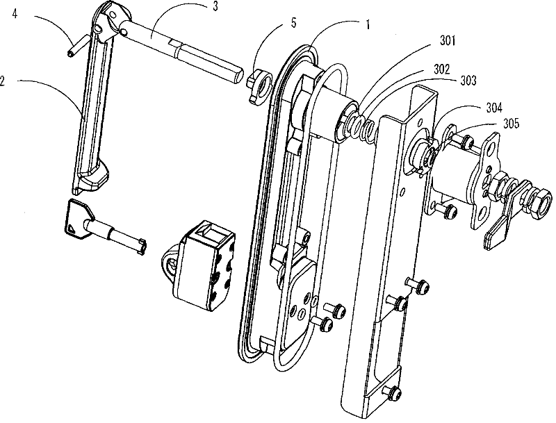
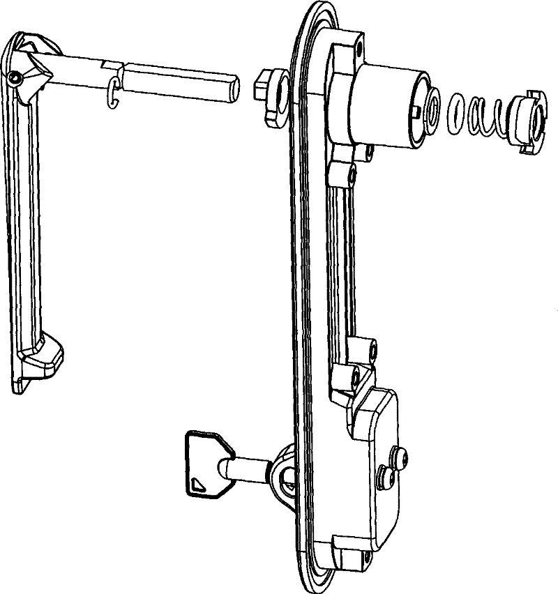
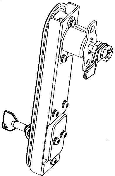
[0029] Such as Figure 1a , Figure 1b , Figure 2a , Figure 2b Shown is the first embodiment of the present invention, for the sake of clarity, Figure 1b , Figure 2b Part of the lock body is removed, and the cabinet lock handle shaft sealing structure includes lock body 1, handle 2 and handle shaft 3, handle 2 and handle shaft 3 are hinged through pin 4, and handle shaft 3 passes through lock body 1 The shaft installation hole 102 on the top is installed on the lock body 1, and the handle shaft 3 is driven by the handle 2 to rotate to realize the opening and locking of the cabinet. A handle shaft lifting mechanism is provided between the handle 2 and the handle shaft 3 to When closing the lock, press the handle 2 and lift the handle shaft 3. After the handle shaft 3 passes through the installation hole on the lock body 1, there is a seal ring 301 on it, and the corresponding seal ring part on the lock body is provided with a tapered seal ring Groove 101 is used to acco...


PUM


Abstract

The invention discloses a shaft seal structure of cabinet lock handgrip, which comprises a lock, a handgrip, and a handgrip shaft, wherein the handgrip is hinged with the handgrip shaft, the handgrip shaft passes through a mounting hole on the lock and is mounted on the lock, the handgrip drives the handgrip shaft to rotate to realize the open and lock of the cabinet, a handgrip shaft lifting mechanism is arranged between the handgrip and the handgrip shaft so as to press down the handgrip and lift the handgrip shaft when closing the lock, the handgrip shaft is sleeved with a sealing ring after passing through the mounting hole on the lock, the part on the lock corresponding to the sealing ring is provided with a sealing ring mount groove so as to accommodate the sealing ring, the height of the sealing ring mounting groove is less than that of the sealing ring, the handgrip is attached to the sealing ring and is sleeved with a gasket and a spring, the upper end of the spring is attached to the gasket, and the lower end of the spring is downward limited on the handgrip shaft in axial direction, when the handgrip is pressed down, the handgrip shaft lifting mechanism lifts the handgrip shaft to compact the spring to generate distortion, and the elastic force generated by the spring distortion is transmitted to the sealing ring to generate deformation under the extrusion of the gasket and the sealing ring mounting groove.

Description

technical field [0001] The invention relates to the field of cabinet locks, in particular to a sealing structure of a cabinet lock. Background technique [0002] At present, an important reason for the poor waterproof performance of outdoor cabinet locks is that the gap between the handle shaft and the lock body is not well sealed, and water can enter the cabinet from the gap between the handle shaft and the lock body, so that the waterproof and dustproof level of the entire cabinet will be reduced; At present, the seal form between the handle shaft and the lock body hole usually used by locks is that the handle shaft seal ring is fixed on the handle shaft, and the seal ring cooperates with the lock body hole gap, and the seal ring and the lock body hole are filled with Lubricating oil, use lubricating oil to ensure waterproof and the feeling of pressing down the handle is not stagnant. However, when the cabinet is in a very harsh outdoor environment such as high temperature...

Claims


Application Information

Patent Timeline
Patent Type & Authority Patents(China)
IPC IPC(8): E05B1/00F16J15/18
Inventor 刘磊
Owner 中兴新通讯有限公司
Why Eureka
Try Eureka