Eccentric gravity type yarn tension mechanism used in winding machine

A yarn tension, gravity type technology, applied in the field of eccentric gravity type yarn tension mechanism, can solve the problems of high preparation and maintenance cost, complex electrical component structure, poor stability and reliability, etc., and achieves low preparation and maintenance cost, Simple structure, high stability and reliability

Active Publication Date: 2021-11-09
山东杰瑞纺织科技有限公司
View PDF14 Cites 0 Cited by
  • Summary
  • Abstract
  • Description
  • Claims
  • Application Information

AI Technical Summary

Problems solved by technology

[0007] The invention provides an eccentric gravity type yarn tension mechanism used in a winding machine, which has the ability to adjust the tension of the yarn by using gravity, has a simple structure, and no longer needs to be equipped with various electrical components and its control devices. The appearance of the spring structure avoids the occurrence of elastic vibration, high stability and reliability, and it can be locked when the yarn stops feeding to prevent the yarn on the yarn wheel from becoming knotted due to loosening and falling off. Advantages, solve the complex structure of the electrical components inside the existing electronic tensioner and need to be equipped with a specific control device and control program, the cost of preparation and maintenance is relatively high, and the control of the tension rod is realized by the tension spring, so that it is Due to the frequent changes of the yarn feed speed in the process of use, different degrees of elastic vibration occur, and the stability and reliability are poor.

Method used


Image

  • Eccentric gravity type yarn tension mechanism used in winding machine
  • Eccentric gravity type yarn tension mechanism used in winding machine
  • Eccentric gravity type yarn tension mechanism used in winding machine

Examples


Embodiment Construction

[0024] The following will clearly and completely describe the technical solutions in the embodiments of the present invention with reference to the accompanying drawings in the embodiments of the present invention. Obviously, the described embodiments are only some, not all, embodiments of the present invention. Based on the embodiments of the present invention, all other embodiments obtained by persons of ordinary skill in the art without making creative efforts belong to the protection scope of the present invention.

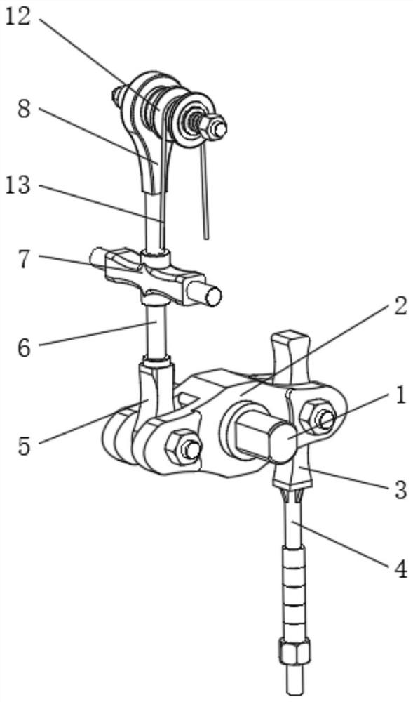
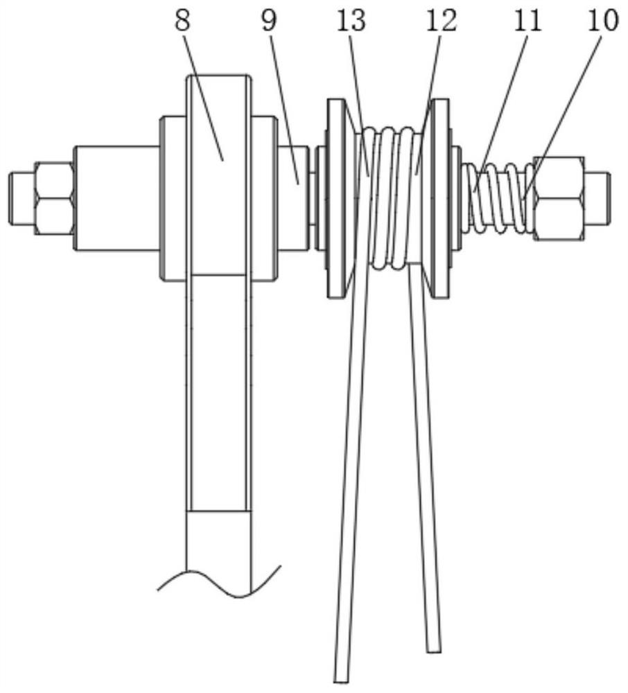
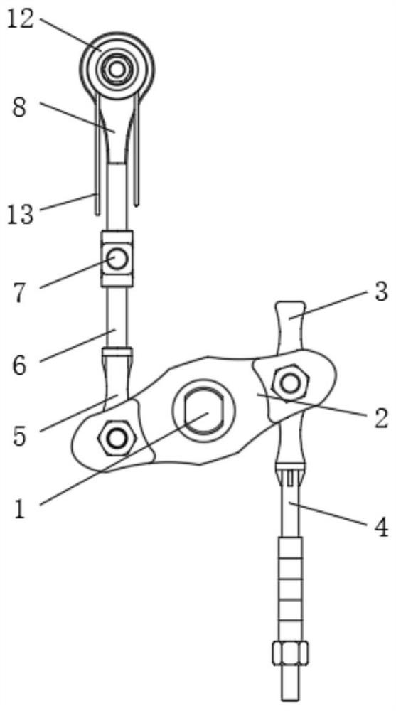
[0025] see Figure 1-2 , an eccentric gravity type yarn tension mechanism used in a winding machine, comprising a fixed shaft 1, the middle part of the outer surface of the fixed shaft 1 is movably sleeved with a balance weight 2, and the two sides of the outer surface of the fixed shaft 1 are respectively fixedly installed on On the tension control frame, the inner pin on one side of the balance weight 2 is connected with the fixed connecting rod I3, and the ...


PUM


Abstract

The invention relates to the technical field of yarn tensioning equipment, and discloses an eccentric gravity type yarn tension mechanism used in a winding machine. The mechanism comprises a fixed shaft, the middle part of the outer surface of the fixed shaft is movably sleeved with a balance block, the interior of one side of the balance block is in pin joint with a fixed connecting rod I, and the bottom end of the fixed connecting rod I is fixedly provided with a counterweight rod; and a fixed connecting rod II is in pin joint in the other side of the balance block, and a transmission connecting rod is fixedly mounted at the top end of the fixed connecting rod II. According to the eccentric gravity type yarn tension mechanism used in the winding machine, connecting mechanisms at the two ends of yarn and the winding direction of the connecting mechanisms are arranged, so that it is ensured that the yarn can generate extrusion component force towards the right side in the axial direction of a connecting shaft when the yarn is fed and stressed, when the yarn is not fed and stressed, the yarn moves towards the left side under the elastic force effect of a locking spring, the friction locking action is generated between a transmission pulley and a friction shaft sleeve, so that the action of each part on the tension mechanism can be stably and effectively implemented.

Description

technical field [0001] The invention relates to the technical field of yarn tensioning equipment, in particular to an eccentric gravity yarn tensioning mechanism used in a winding machine. Background technique [0002] Tensioners are commonly used parts in yarn textile machinery because when the tension on the yarn is too large, the yarn is prone to breakage; when the tension is too small, the yarn is prone to knotting, and The use of the tensioner can regulate the tension of the yarn in real time, so that the feeding strength of the yarn can be kept constant, thereby effectively improving the production efficiency and quality of the yarn weaving. [0003] Among them, the electronic tensioner is the most conventional form at present. Its internal electrical components are complicated in structure and need to be equipped with specific control devices and control programs. The preparation and maintenance costs are relatively high, and the control of the tension rod is realized...

Claims


Application Information

Patent Timeline
IPC IPC(8): B65H59/10
CPCB65H59/10
Inventor 董先丽
Owner 山东杰瑞纺织科技有限公司
Why Eureka
Try Eureka