Background magnetic resonance imaging

A magnetic resonance imaging and imaging technology, which is applied in the direction of magnetic resonance measurement, measurement using nuclear magnetic resonance imaging system, measurement of magnetic variables, etc. and other problems to achieve the effect of reducing the inspection time

Inactive Publication Date: 2009-04-29
KONINKLIJKE PHILIPS ELECTRONICS NV
View PDF0 Cites 9 Cited by
  • Summary
  • Abstract
  • Description
  • Claims
  • Application Information

AI Technical Summary

Problems solved by technology

These solutions work to reduce scan time, but not the period of scanner inactivity between two imaging process segments
Moreover, this solution cannot be used for all image acquisitions, and for other cases can adversely affect image quality, such as contrast

Method used


Image

  • Background magnetic resonance imaging
  • Background magnetic resonance imaging

Examples


Embodiment Construction

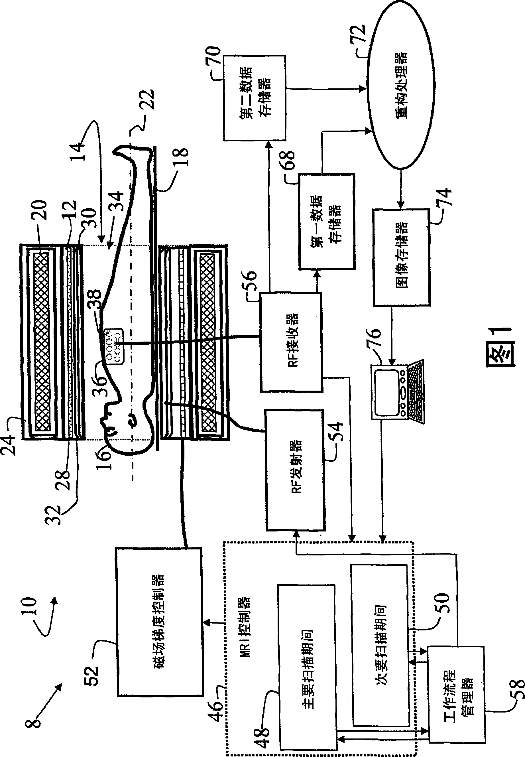
[0015] Referring to FIG. 1 , a magnetic resonance imaging system 8 includes a scanner 10 including a housing 12 defining an examination region 14 in which a patient or other imaging subject 16 is positioned on a patient or subject support or couch 18 . A main magnet 20 arranged in the housing 12 generates a main magnetic field B in the examination region 14 0 . Typically the main magnet 20 is a superconducting magnet surrounded by a cryogenic enclosure 24; however, resistive or permanent main magnets may also be used. Magnetic field gradient coils 28 are arranged in or on housing 12 to superimpose selected magnetic field gradients on the main magnetic field in examination region 14 .

[0016] An integral radio frequency coil 30, such as a stripline coil, a SENSE coil element, a birdcage coil, etc., surrounded by an RF shield 32 is arranged in the housing 12 to inject radio frequency excitation pulses into the examination region 14 and detect the resulting magnetic field. res...


PUM


Abstract

An imaging controller (46) performs data acquisition in first and second scanning processes (48, 50), the first scanning process (48) including a set of data acquisitions (92, 96, 106, 122, 124, 126, 128, 130) and periods of inactivity (90, 94, 102, 110, 142, 152). A workflow manager (58) monitors the first scanning process (48), detects the periods of inactivity (90, 94, 102, 110, 142, 152) and enables data acquisition of the second scanning process (50) when the first scanning process (48) is inactive.

Description

technical field [0001] The present application relates to diagnostic imaging systems and methods. It finds particular application in, and is described with particular reference to, improving the throughput of magnetic resonance imaging (MRI) systems. However, it can also be applied to positron emission tomography (PET), single photon emission tomography (SPECT) systems, computed tomography (CT) systems, and the like. Background technique [0002] Magnetic resonance imaging scanners typically include a main magnet (which is usually superconducting) that generates a spatially and temporally constant magnetic field B across the examination region 0 . Usually radio frequency (RF) coils, such as integral coils, local coils, etc., and transmitters are tuned to be in the magnetic field B 0 The resonant frequency of the dipole imaged in . Coils and transmitters are used to excite and manipulate dipoles. Spatial information is encoded by driving the gradient coils with current t...

Claims


Application Information

Patent Timeline
Patent Type & Authority Applications(China)
IPC IPC(8): G01R33/54
CPCG01R33/543G01R33/54
Inventor A·J·马丁O·M·韦伯
Owner KONINKLIJKE PHILIPS ELECTRONICS NV
Why Eureka
Try Eureka