Coiling temperature control device and control method

A technology for coiling temperature and control devices, which is applied in temperature control and electric temperature control, etc., which can solve the problems of excessive calculation amount and undisclosed difference calculation time interval determination, etc.

Inactive Publication Date: 2012-11-28
HITACHI LTD
View PDF5 Cites 0 Cited by
  • Summary
  • Abstract
  • Description
  • Claims
  • Application Information

AI Technical Summary

Problems solved by technology

However, there is no disclosure of a technology for determining the time interval for difference calculation to an appropriate value.
In addition, for all the regions partitioned in the longitudinal direction of the steel plate, since the header pattern is calculated after the coiling temperature is calculated, there is still the problem of excessive calculation

Method used


Image

  • Coiling temperature control device and control method
  • Coiling temperature control device and control method
  • Coiling temperature control device and control method

Examples


Embodiment 1

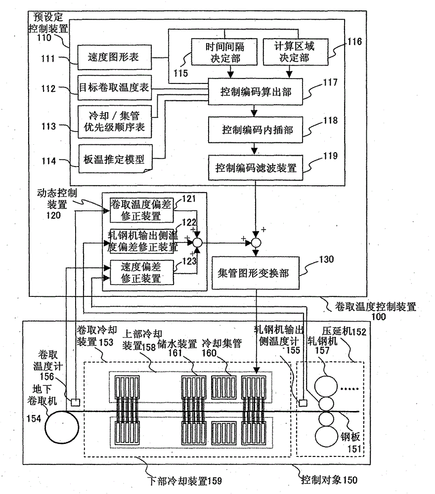
[0048] figure 1 An example of the coiling temperature control system of the present invention is shown. The coiling temperature control device 100 receives various signals from the control object 150 and outputs a control signal to the control object 150 . First, the configuration of the control object 150 will be described. In the present embodiment, the control object 150 is a coiling temperature control device for hot rolling, and the coiling cooling device 153 is used to cool the steel plate 151 rolled by the rolling mill 157 of the rolling section 152 at a temperature of about 900° C. The coiler 154 coils. In the tandem rolling, about seven rolling mills are used for continuous rolling, so the rolling mill 157 in the figure corresponds to the final rolling stand. In addition, a rolling table like a furnace rolling mill may reciprocate rolling, and any one of them can be applied to the present invention.

[0049] The coiling cooling device 153 includes an upper cooling...

Embodiment 2

[0128] The following shows an example in which the time interval of the difference calculation is optimized every time according to the current steel plate speed. Figure 16 The processing of the time interval determination unit 115 in this case is shown. The time interval determination unit 115 is activated every time a new calculation time is received from the control code calculation unit 117, and the time interval is calculated and output. In S16-1, the current calculation time is read from the control code calculation unit 117, and the board speed at that time is calculated. In S16-2, the standard time interval is calculated according to the formula (2) based on the plate speed and the nozzle spacing in the longitudinal direction of the steel plate. Then, based on the standard time interval, the time interval for the difference calculation is calculated according to the formula (3), and is output to the control code calculation unit 117 .

[0129] In the first embodimen...

Embodiment 3

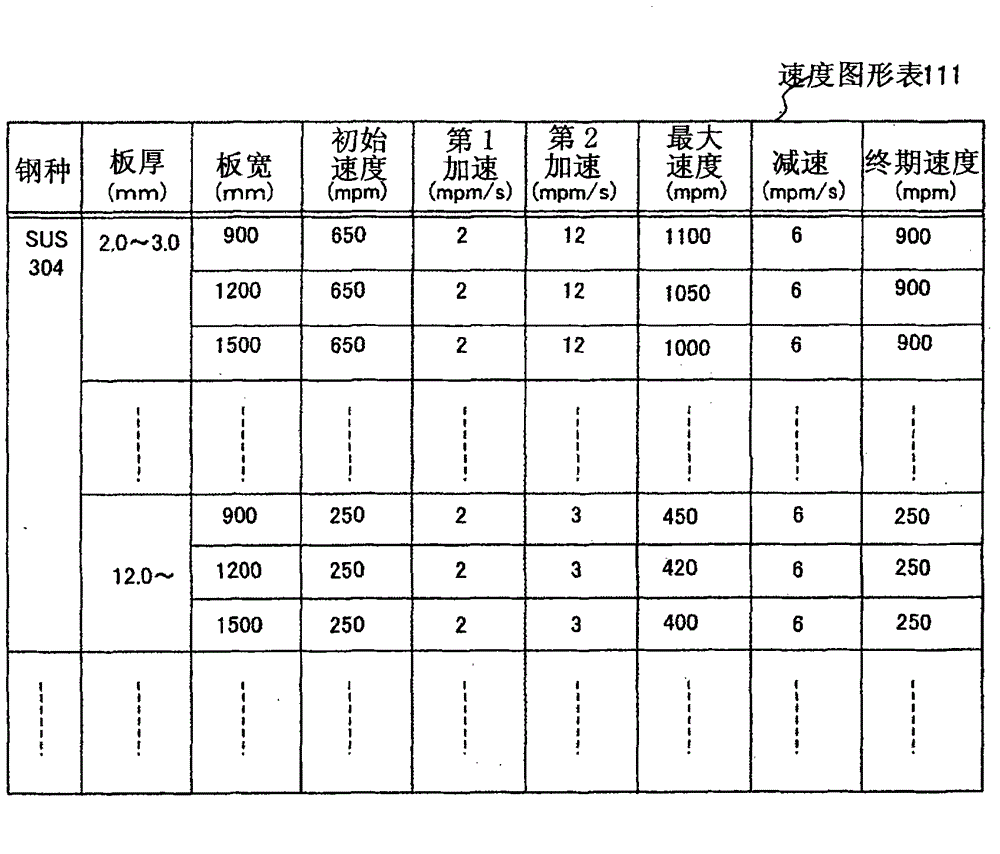
[0131] Next, an example in the case where the calender is a furnace rolling mill will be shown. Figure 17 The structure of the speed graph table 111 corresponding to rolling in a furnace coil is shown. With respect to the steel grade, plate thickness, and plate width, the front end of the steel plate 151 is rolled from the calender 157 to the speed at which it is coiled on the downcoiler 154 (initial speed), and then the constant speed after being rapidly accelerated ( maximum speed), the rear end of the steel sheet 151 is rapidly decelerated before being rolled out from the rolling mill 157, and stratified to the speed (final speed) before being coiled by the downcoiler 154.

[0132] The time interval determination unit 115 , the calculation area determination unit 116 , and the control code calculation unit 117 determine the steel type, plate thickness, and plate width of the coil, and extract the corresponding speed pattern from the speed pattern table 115 . For example, ...


PUM


Abstract

The invention provides a hot rolling coiling temperature control device for implementing high precision cooling control through a simple calculation. When the coiling temperature is inferred from a difference calculation of a control coding operation device (117) in a presetting control device (110), a difference time interval is set an essential sufficient value according to the ratio of a steelplate speed and a manifold space by using a time interval determination device (115), thereby eliminating invalid calculations. Moreover the coiling temperature presumption and calculation and the calculation determined by a manifold graphic are carried out aiming at parts with limited steel plate vertical direction determined by the steel plate speed variation graphic by using a calculation region determination part (116). The manifold graphic is determined by a simple interpolation calculation for other parts, thereby a control precision is not sacrificed and the calculation amount is reduced.

Description

technical field [0001] The present invention relates to a coiling temperature device of a hot rolling production line and a control method thereof, and relates to a coiling temperature control method suitable for making the coiling temperature consistent with the target temperature through simple calculation. Background technique [0002] As a conventional method for controlling the coiling temperature, for example, Patent Document 1 discloses a method of setting a cooling model based on information on the rolled material in accordance with a velocity pattern of the rolled material obtained before the start of cooling, and based on the rolling during rolling The speed of the material is controlled according to the cooling pattern. [0003] In addition, Patent Document 2 describes a coiling temperature control method in which a steel sheet is divided in the longitudinal direction according to a rolling material cooling device, and the divided area (section) is used as a mater...

Claims


Application Information

Patent Timeline
Patent Type & Authority Patents(China)
IPC IPC(8): B21B37/76G05D23/19
Inventor 鹿山昌宏栗林健
Owner HITACHI LTD
Why Eureka
Try Eureka