Mechanism for controlling position of optical element

A technology of optical components and control mechanisms, applied in the direction of optical components, optics, installation, etc., can solve the problems of unobtainable optical performance, and achieve the effects of low power consumption, space saving, and small load changes

Inactive Publication Date: 2013-07-24
HOYA CORP
View PDF1 Cites 0 Cited by
  • Summary
  • Abstract
  • Description
  • Claims
  • Application Information

AI Technical Summary

Problems solved by technology

[0006] In addition, although the variable range of the spring load can be reduced by reducing the amount of movement of the optical element holding member, the amount of movement of the optical element holding member (that is, the amount of movement of the optical element supported by the optical element holding member) from Determined from the outset to meet the need for optical performance that could not be obtained if the amount of movement of the optical element holding part was restricted

Method used


Image

  • Mechanism for controlling position of optical element
  • Mechanism for controlling position of optical element
  • Mechanism for controlling position of optical element

Examples


Embodiment Construction

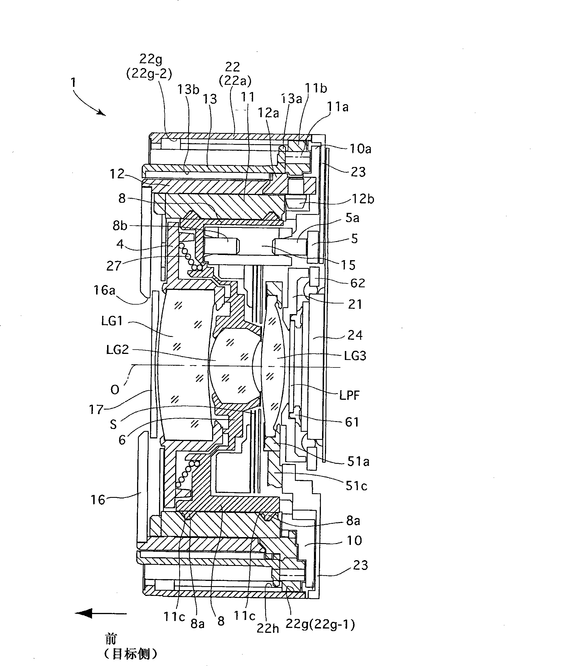
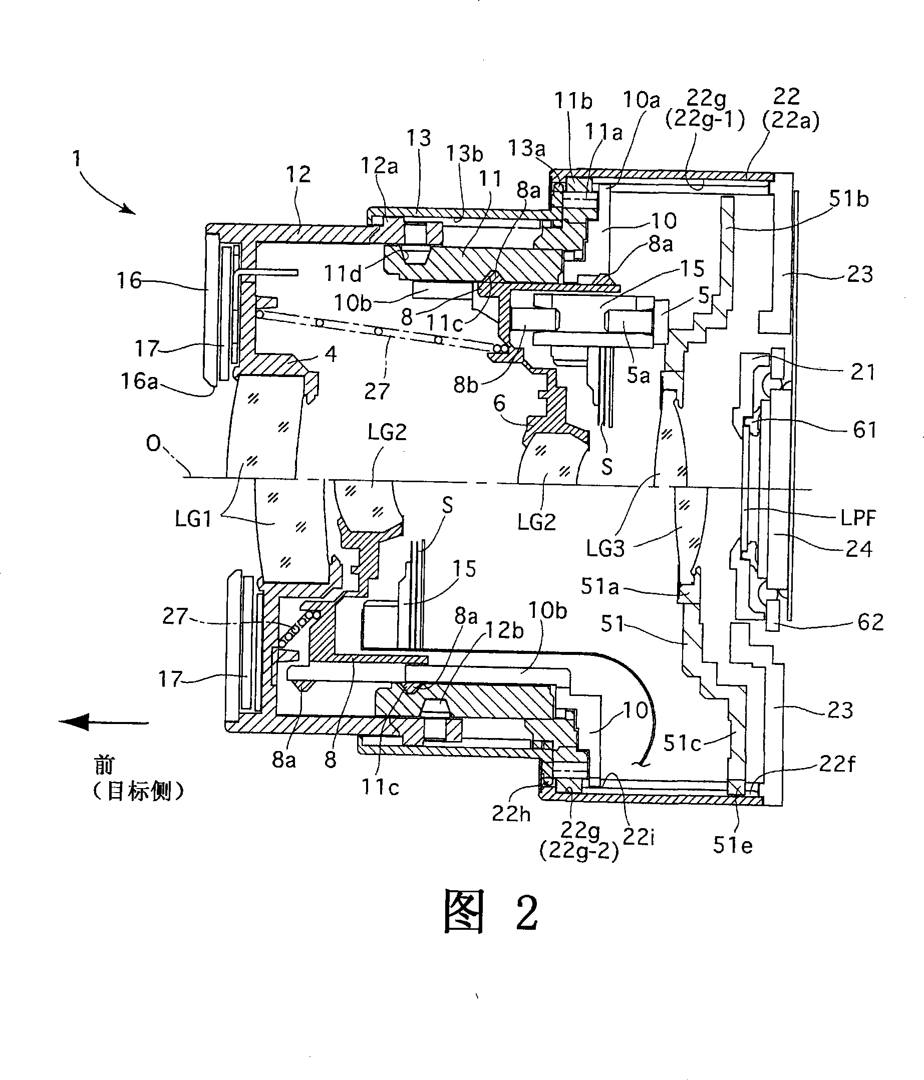
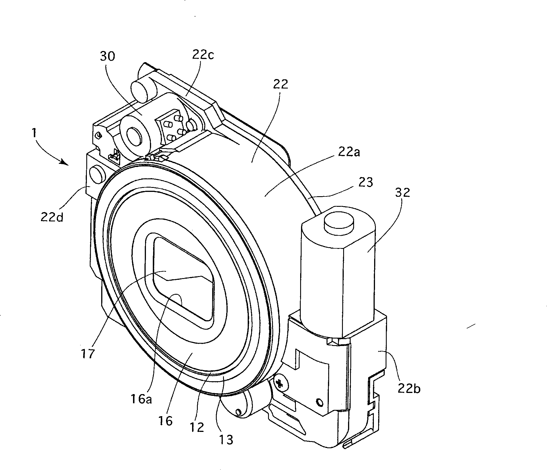
[0056] First, the following will mainly be based on figure 1 7 to discuss the overall structure of the zoom lens barrel 1 to which the optical element position control mechanism of the present invention is applied. figure 1 and Fig. 2 have provided the sectional view of zoom lens barrel 1 respectively, figure 1 It shows that the zoom lens barrel 1 is in the retracted state of the lens barrel, and no photos are taken in this state. The upper half of the sectional view in Fig. 2 shows that the zoom lens barrel 1 is at the wide-angle end, and the lower part of the sectional view in Fig. 2 Half shows the zoom lens barrel 1 at the telephoto end. image 3 with Figure 4 is a perspective view of the zoom lens barrel 1 in the lens barrel retracted state, Figure 5 with Image 6 It is a perspective view of the zoom lens barrel 1 in a ready-to-shoot state.

[0057] The zoom lens barrel 1 has a photographic optical system including, in order from the object side, a first lens group ...


PUM


Abstract

An optical element position control mechanism includes an optical element holding member which holds an optical element of a photographing system and is guided in an optical axis direction; a drive mechanism for moving the optical element holding member in the optical axis direction; and a biasing device including an arm which is swingable about a swing axis, the swing axis being substantially orthogonal to the optical axis, and the arm extending substantially orthogonal to the swing axis and having a free end portion which engages with the optical element holding member to bias the optical element holding member in the optical axis direction.

Description

technical field [0001] The present invention relates to a mechanism for controlling the position of an optical element in an optical device, and more particularly, to a structure for providing an optical element holding member that can be moved along the optical axis by a biasing force in the direction of movement of the optical element holding member. direction to move. Background technique [0002] In an optical device such as a camera, it often happens that a biasing force in the direction of the optical axis is applied to an optical element holding member that supports the optical element and can move in the direction of the optical axis so that the optical element The holding member has a function as part of a driving mechanism that drives the optical element holding member, eliminates a backlash in the driving mechanism, or stabilizes the position of the optical element holding member. The biasing means for biasing the optical element holding member is usually made of...

Claims


Application Information

Patent Timeline
Patent Type & Authority Patents(China)
IPC IPC(8): G02B7/04G02B7/02
Inventor 野村博
Owner HOYA CORP
Why Eureka
Try Eureka