
Display system and method for detecting pointed position

A technology for displaying systems and indicating positions, applied in the input/output process of data processing, instruments, electrical digital data processing, etc.

Inactive Publication Date: 2012-05-30
SHARP KK
View PDF7 Cites 0 Cited by
  • Summary
  • Abstract
  • Description
  • Claims
  • Application Information

AI Technical Summary

Problems solved by technology

[0011] On the other hand, such as Figure 25(a) and Figure 25 As shown in (b), when the distance between the display device 102 and the operating device 101 is relatively short, according to the indicated position of the operating device 101, the LED module 103 is not accommodated within the photographable range of the imaging element
Furthermore, when the LED module 103 is not housed within the photographable range, the pointing position of the operation device 101 cannot be detected.

Method used


Image

  • Display system and method for detecting pointed position
  • Display system and method for detecting pointed position
  • Display system and method for detecting pointed position

Examples


Embodiment approach 1

[0047] One embodiment of the present invention will be described.

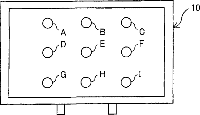
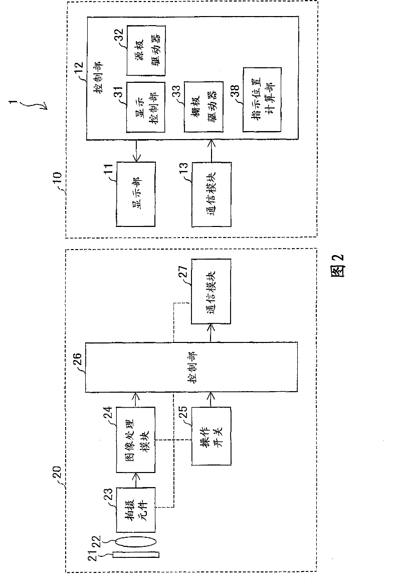
[0048] figure 2 It is a block diagram showing a schematic configuration of the display system 1 of the present embodiment. As shown in the figure, the display system 1 includes a liquid crystal display device 10 and an operation device 20 .

[0049] The liquid crystal display device 10 includes a display unit 11 , a control unit 12 and a communication module 13 .

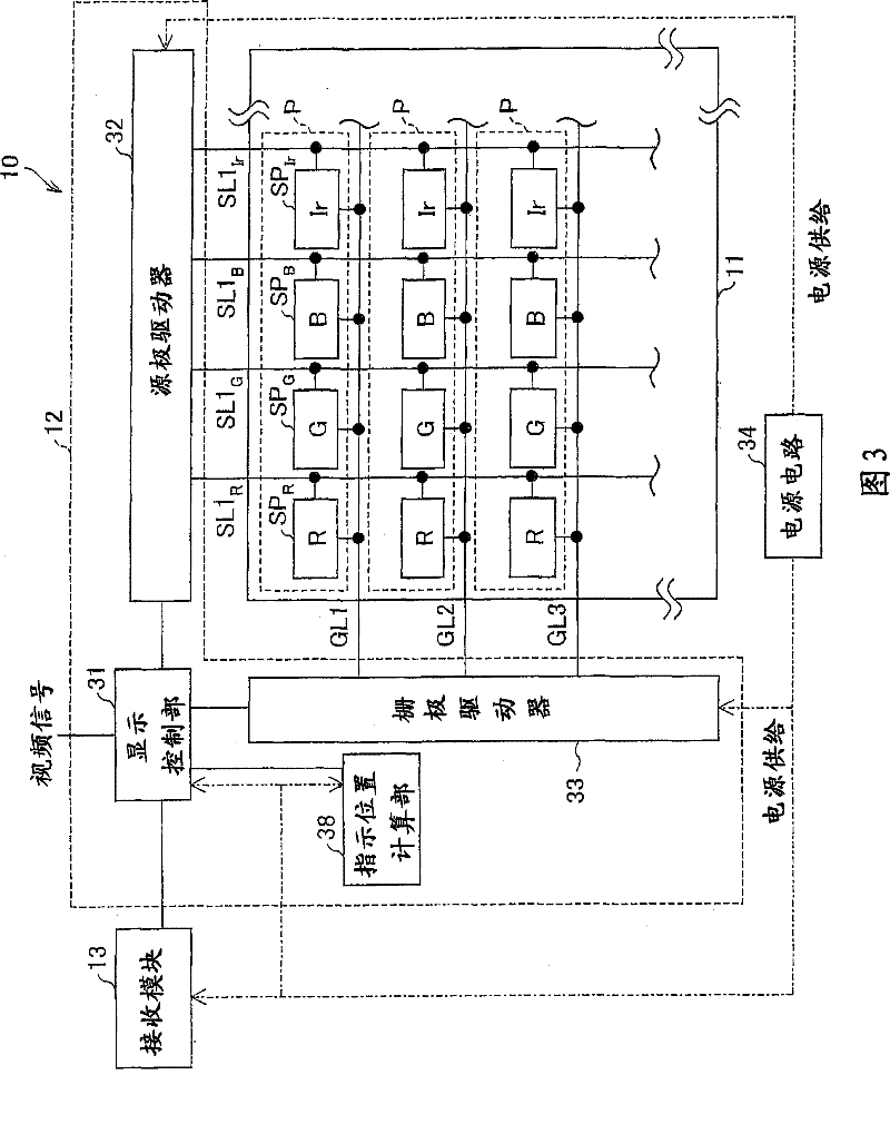
[0050] image 3 is a block diagram showing a schematic configuration of the liquid crystal display device 10, Figure 4 yes means image 3 A schematic diagram of a schematic configuration of each sub-pixel in the liquid crystal display device 10 shown.

[0051] like image 3 As shown, the liquid crystal display device 10 is provided with: a display portion (display panel) 11, which is composed of sub-pixels (sub-pixels) of four colors: R (red), G (green), B (blue), and Ir (infrared). A plurality of pixels P composed of SPR, SPG, SPB, and SPI...

Embodiment approach 2

[0129] Next, other embodiments of the present invention will be described. In addition, for convenience of description, components having the same functions as those in Embodiment 1 are denoted by the same reference numerals, and description thereof will be omitted.

[0130] In this embodiment, the pointing position in the coordinate system of the display screen and the distance between the display screen and the operating device 20 are calculated based on the imaging result by the operating device 20 , and the display position of the bright spot is controlled based on the calculation result. Thus, in the present embodiment, even when the distance between the operation device 20 and the display screen is very short, the area on the display screen where the operation device 20 can make instructions can be further enlarged.

[0131] Figure 20It is a block diagram showing a schematic configuration of the display system 1b of this embodiment. As shown in the figure, the display...


PUM


Abstract

A plurality of infrared-light-emitting areas are displayed in a display screen of a liquid crystal display apparatus in a method that allows each of the infrared-light-emitting areas to be distinguished. Then, an image in a direction of a pointed position is captured by an operating device. Further, a predetermined number of infrared-light-emitting areas are selected from the infrared-light-emitting areas included in thus captured image. Based on a result of distinguishing each of the selected infrared-light-emitting areas and a position of each of the selected infrared-light-emitting areas, a pointed position on the display screen is calculated. This makes it possible to properly detect the pointed position on the display screen pointed by the operating device, regardless of a distance between the operating device and the display apparatus.

Description

technical field [0001] The present invention relates to a display system capable of detecting an indicated position on a display screen indicated by an operating device such as a pointer, and a method for detecting the indicated position. Background technique [0002] In recent years, along with the thinning of displays such as liquid crystal displays and plasma displays, displays with larger screen sizes have also become popular. [0003] These thin and large displays are often used, for example, as displays for conferences, product presentations, etc., or displays for video games. Furthermore, in the case of such use, an operation device such as a pointer is used to designate a desired point (position or location) on an image displayed on a display and perform an operation. [0004] For example, Patent Document 1 (Japanese Laid-Open Patent Publication No. 2007-66080 (publication date: March 15, 2007)) discloses a technique of driving and disposing the LEDs in different b...

Claims


Application Information

Patent Timeline
Patent Type & Authority Patents(China)
IPC IPC(8): G06F3/042G06F3/038G06F3/033G06F3/0346G06F3/041
CPCG06F3/0412G06F3/042G06F3/0321G06F3/0325
Inventor 森本淳寿大平雅和广畑仁志
Owner SHARP KK
Learn More