
Optical devices, retina projection display devices, head mounted display devices

A technology of optical devices and light source parts, applied in optics, optical components, instruments, etc., can solve problems such as diameter expansion and inability to accurately detect pupil positions

Active Publication Date: 2022-07-08
RICOH KK
View PDF29 Cites 0 Cited by
  • Summary
  • Abstract
  • Description
  • Claims
  • Application Information

AI Technical Summary

Problems solved by technology

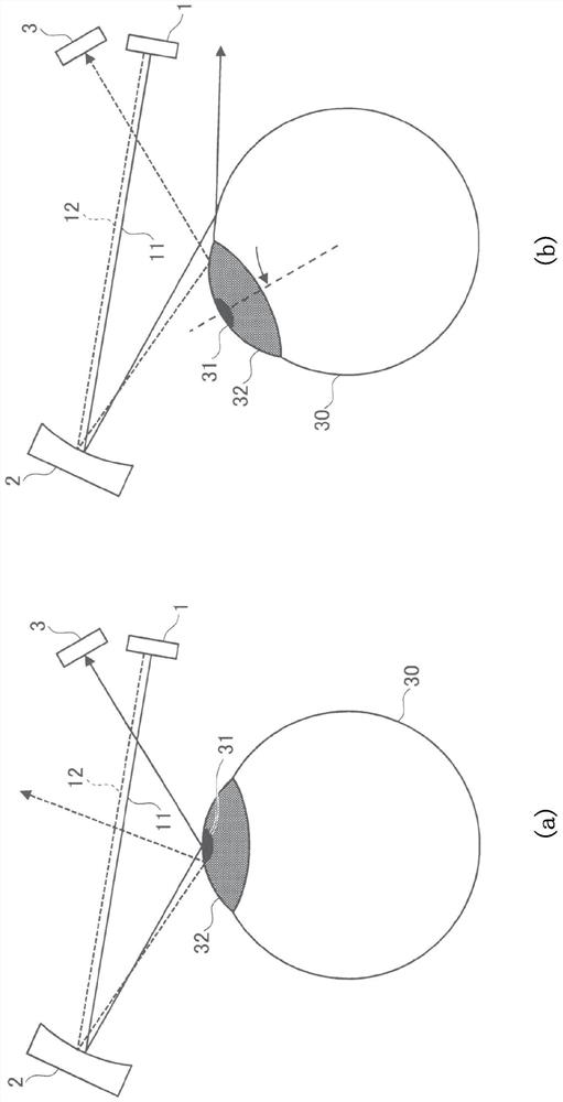
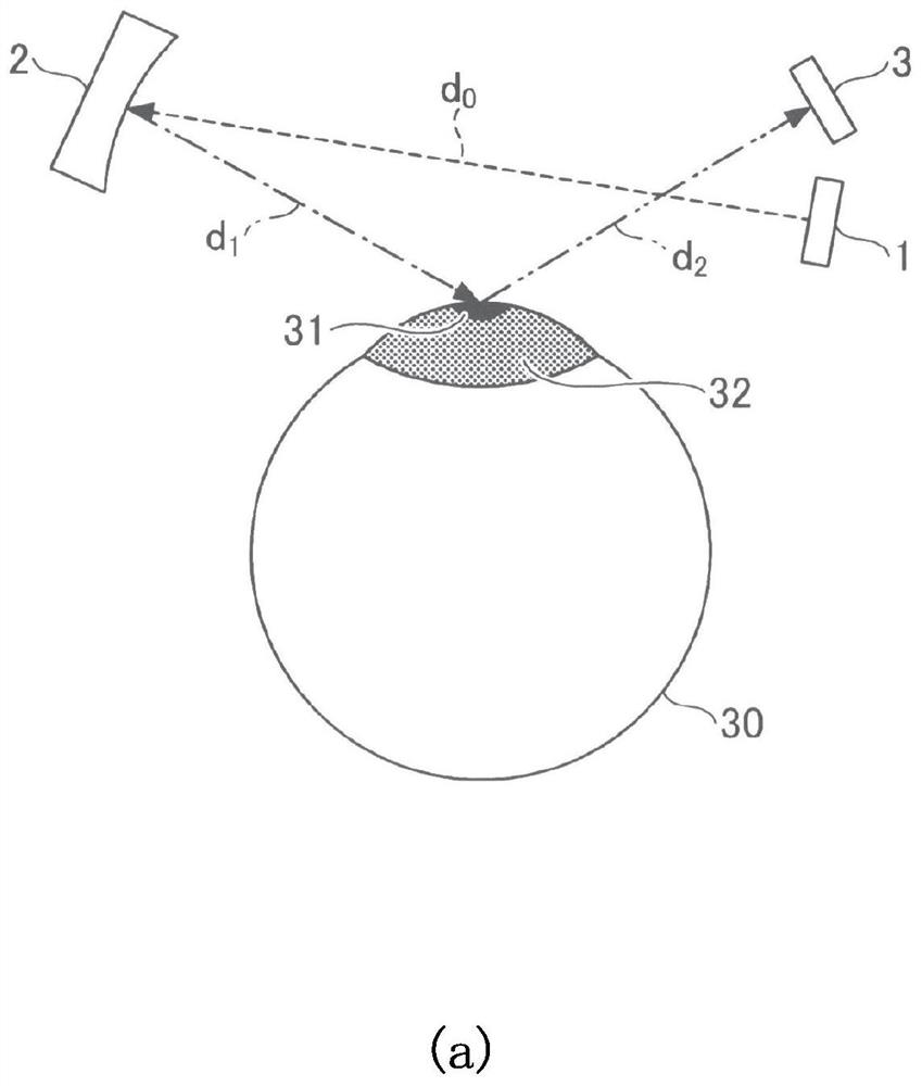
[0004] However, in the techniques of Patent Document 1 and Patent Document 2, the reflection of the large curvature of the eyeball or the cornea will enlarge the diameter of the laser beam on the light receiving surface of the photodetector, and sometimes the pupil position cannot be accurately detected.

Method used


Image

  • Optical devices, retina projection display devices, head mounted display devices
  • Optical devices, retina projection display devices, head mounted display devices
  • Optical devices, retina projection display devices, head mounted display devices

Examples


no. 1 approach

[0035]

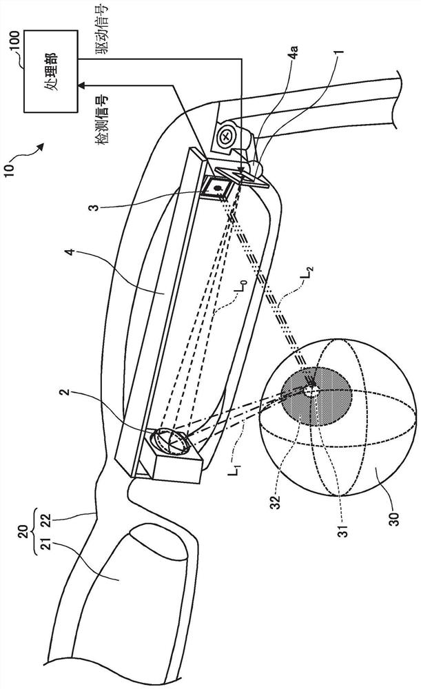
[0036] figure 1 It is a schematic diagram for explaining an example of the configuration of the pupil position detection device according to the present embodiment.

[0037] like figure 1 As shown, the pupil position detection device 10 includes a VCSEL (Vertical Cells Surface Emitting Laser) 1 as an example of a light source unit, a concave mirror 2 , a PSD (Position Sensitive Detector) 3 , and a processing unit 100 .

[0038] The VCSEL1 , the concave mirror 2 and the PSD3 are arranged on the optical system support 4 , and the optical system support 4 is tiltably fixed on the eyeglass frame 22 of the eyeglass type support body 20 including the eyeglass lens 21 and the eyeglass frame 22 through the ball joint 4a. The inclination of the optical system support body 4 can be adjusted by the ball joint 4a. As the ball joint 4a constituting the micro-adjustment mechanism, in addition to being fixed by the mechanical pressure acting between the spherical structure and i...


PUM


Abstract

The present invention relates to an optical device, a retinal projection display device, a head-mounted display device and an optometry device, the purpose of which is to accurately detect the pupil position. In this regard, the present invention provides an optical device, which includes a light source part for emitting light; a condensing reflection element for converging the light from the light source part and reflecting it on a surface to be irradiated with curvature and a position detection element for detecting the position of the reflected light from the irradiated surface.

Description

technical field [0001] The present invention relates to an optical device, a retinal projection display device, a head-mounted display device, and an optometry device. Background technique [0002] With the continuous development of pupil position (line of sight) detection technology, it is expected to be used in various applications such as interface for electronic equipment control, support for image formation of wearable displays such as head-mounted displays, line-of-sight data collection for skilled technicians, and product attention analysis. to get the application. In this regard, the pupil position detection device is required to have detection response performance and to reduce the size and weight of the detection device. [0003] In response to such a demand, the prior art, such as Patent Document 1 (US2016 / 0166146) and Patent Document 2 (US2017 / 0276934), discloses that by detecting the temporal change of the reflected light intensity of laser light scanning the s...

Claims


Application Information

Patent Timeline
Patent Type & Authority Patents(China)
IPC IPC(8): G02B27/00G02B27/01
CPCG02B27/0093G02B27/0172G02B2027/0178G06F3/013G02B26/0816G02B26/125G02B2027/014G02B2027/0174G02B2027/0187G02B27/18G02B27/0176G02B27/14
Inventor 三宫俊下川达也安达一彦田中秀铃木修一
Owner RICOH KK
Learn More