Time synchronization method and apparatus

A time synchronization and time technology, applied in the field of communication, to achieve the effect of reducing phase delay

Active Publication Date: 2012-10-10
ZTE CORP
View PDF0 Cites 0 Cited by
  • Summary
  • Abstract
  • Description
  • Claims
  • Application Information

AI Technical Summary

Problems solved by technology

[0006] The present invention is proposed in view of the problem that the cumulative effect of phase transfer in the related art will lead to a relatively obvious phase delay. Therefore, the present invention aims to provide a time synchronization method and device to solve the above problems

Method used


Image

  • Time synchronization method and apparatus
  • Time synchronization method and apparatus
  • Time synchronization method and apparatus

Examples


Embodiment Construction

[0028] Functional Overview

[0029] Considering that the cumulative effect of phase transfer in the related art will lead to a relatively obvious phase delay problem, an embodiment of the present invention provides a time synchronization method and device, which realize time network synchronization on the basis of a clock synchronization network, and edge nodes Compatibility with non-clock synchronous networks is achieved, thereby reducing phase delay. It should be noted that, in the case of no conflict, the embodiments in the present application and the features in the embodiments can be combined with each other. The present invention will be described in detail below with reference to the accompanying drawings and examples.

[0030] method embodiment

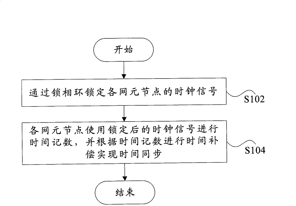
[0031] According to an embodiment of the present invention, a time synchronization method is provided. figure 1 It is a flowchart of a time synchronization method according to an embodiment of the present invention. It shou...


PUM


Abstract

The invention discloses a time synchronization method and device. The method includes: using a phase-locked loop to lock clock signal of each network element node; each network element node using locked clock signal to execute time counting, and executing time bias to implement time synchronization on the basis of the time counting. The invention can reduce phase delay.

Description

technical field [0001] The present invention relates to the communication field, in particular to a time synchronization method and device. Background technique [0002] At present, there are two types of time synchronization, one is frequency synchronization, that is, the signals at the source end and the destination end maintain a certain relationship in frequency or phase, that is, the frequencies of the source end and the destination end are within a certain accuracy Keep the same, the phase difference is constant, frequency synchronization is usually also called clock synchronization, for example, synchronous Ethernet, E1 interface clock synchronization, etc.; another kind of synchronization is time synchronization, that is, not only the frequency is the same, but the phase is also the same. [0003] The above-mentioned frequency synchronization and time synchronization are two levels of wireless network synchronization requirements for time. For wireless systems based ...

Claims


Application Information

Patent Timeline
Patent Type & Authority Patents(China)
IPC IPC(8): H04W56/00H04B7/26
CPCH04J3/0688H04J3/0667
Inventor 何力郁志勇苏卉
Owner ZTE CORP
Why Eureka
Try Eureka