Plastic energy management beam

A technology of energy control and energy, which is applied to bumpers and other directions, and can solve problems such as insufficient energy absorption and failure of bumper systems

Inactive Publication Date: 2009-05-13
SHAPE CORP
View PDF5 Cites 6 Cited by
  • Summary
  • Abstract
  • Description
  • Claims
  • Application Information

AI Technical Summary

Problems solved by technology

Those of ordinary skill in the art of bumper manufacturing know that the concept of extruded struts purely from higher strength materials is often a bad idea and, in fact, ofte

Method used


Image

  • Plastic energy management beam
  • Plastic energy management beam
  • Plastic energy management beam

Examples


Embodiment Construction

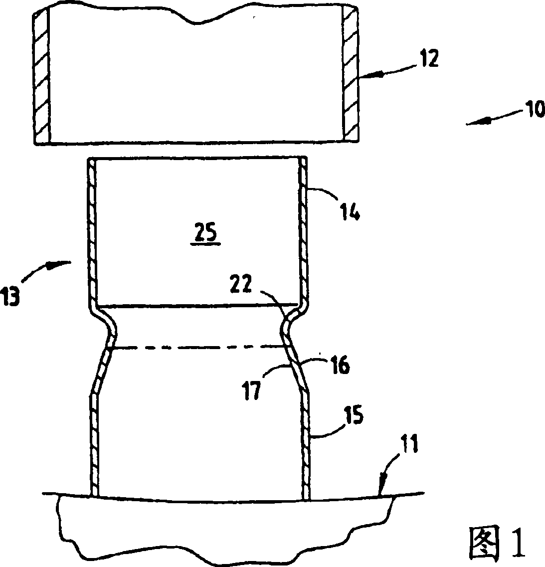
[0058] For purposes of this description, the terms "upper", "lower", "right", "left", "rear", "front", "vertical", "horizontal" and derivatives thereof shall refer to the present invention as oriented in FIG. . However, it will be appreciated that the invention is also capable of various other orientations, except as expressly stated to the contrary. It is also to be understood that the particular devices and processes illustrated in the drawings and described in the following specification are simply exemplary embodiments of the principles of the invention as defined in the appended claims. Accordingly, specific dimensions and other physical characteristics relating to the embodiments disclosed herein are not to be considered limiting, unless the claims expressly state otherwise.

[0059] It is to be noted that the present invention includes energy management technology (EMT) employing thermoplastic and thermosetting polymeric materials with and without fillers and reinforce...


PUM


Abstract

An energy-absorbing system includes a tube made of a continuous polymeric material.The tube has first and second tube sections connected by an intermediate tubesection. By this arrangement, upon the bumper system receiving a longitudinalimpact, the first and second tube sections telescopingly collapse with a predictableand consistent rolling collapse.

Description

[0001] Cross-references in relation to applications [0002] This application claims the benefit of US Provisional Application No. 60 / 607,677, filed September 7, 2004, entitled "Energy Control Beams Made of Plastic," which is incorporated herein by reference in its entirety. [0003] The above application is a continuation-in-part of U.S. Application Serial No. 10 / 997,332, entitled "Tubular Energy Control System for Absorbing Impact Energy," which is a continuation-in-part of U.S. Application Serial No. 10 / 997,332, entitled "Tubular Energy Control System for Absorbing Impact Energy Control System", a continuation of U.S. Application No. 10 / 648,757, filed August 26, 2003, which is a continuation of U.S. Application No. 09 / 964,914, filed September 27, 2001, now titled " Extruded Struts with Different Strength Rings" are continuations-in-part of US Patent No. 6,648,384, the entire contents of which applications are incorporated herein by reference. This application is also a cont...

Claims


Application Information

Patent Timeline
IPC IPC(8): B60R19/26
Inventor S·C·格拉斯哥D·W·希瑟林顿B·W·莱昂斯D·埃文斯R·B·尼斯
Owner SHAPE CORP
Why Eureka
Try Eureka