Apparatus for locking main shaft

A locking device and spindle technology, applied in metal processing equipment and other directions, can solve the problems of unreliable locking, unattainable machining accuracy, affecting the accuracy of the spindle, etc., and achieve the effect of ensuring accuracy, absolutely reliable locking, and simple structure.

Active Publication Date: 2009-05-20
GUANGZHOU WEIJIA MACHINE
View PDF0 Cites 9 Cited by
  • Summary
  • Abstract
  • Description
  • Claims
  • Application Information

AI Technical Summary

Problems solved by technology

[0002] The existing machine tool spindle locking devices are bulky, complex in structure, unreliable in locking, and due to the eccentric error with the spindle during locking, it is easy to affect the accuracy of the spindle; while the high-speed electric spindle for machining centers is generally used for precision CNC machining center, the precision requirements of the spindle are particularly high. If the spindle locking device affects the precision of the spindle, the machining accuracy will not be achieved, and the service life of the spindle bearing and the spindle will be reduced; in addition, most of the electric spindles of high-speed precision machini...

Method used


Image

  • Apparatus for locking main shaft
  • Apparatus for locking main shaft
  • Apparatus for locking main shaft

Examples


Embodiment Construction

[0018] The present invention will be further described below in conjunction with accompanying drawing.

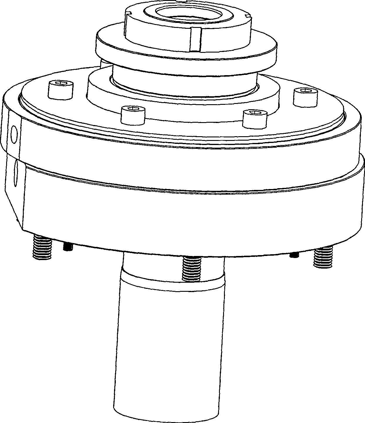
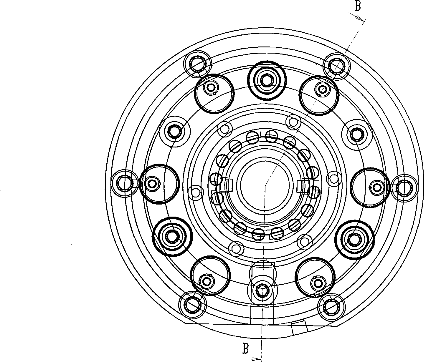
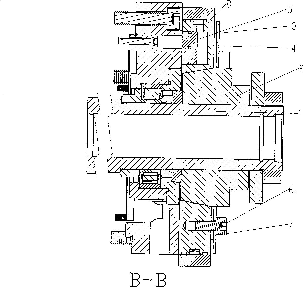
[0019] In the figure: main shaft 1, inner expansion sleeve 2, outer expansion sleeve 3, spring disc 4, piston block 5, locking screw 6, adjusting gasket 7, rear flange 8, fixing column 10, fixing screw 11.

[0020] as attached figure 1 , attached figure 2 , attached image 3 , attached Figure 4 , attached Figure 5 As shown, the main shaft locking device of the present invention is composed of an inner expansion sleeve 2, an outer expansion sleeve 3, a spring disc 4, a piston block 5, a fixed column 10, a fixing screw 11, and a locking screw 6. The inner expansion sleeve and the outer expansion sleeve There are mutually matching taper surfaces between the sleeves. The inner expansion sleeve is arranged outside the rear flange of the main shaft. The inner expansion sleeve is fixed on the main shaft. The inner expansion sleeve can rotate with the main shaft. The outer e...


PUM


Abstract

The invention discloses a spindle locking device and relates to a precise spindle locking device. The spindle locking device consists of an internal expansion sleeve, an external expansion sleeve, a spring disc, a piston block and a fixed post, a fixing bolt and a fixing bolt. The internal expansion sleeve is fixed on a spindle and can rotate together with the internal expansion sleeve. The external expansion sleeve is sleeved on the internal expansion sleeve. Conical surfaces which are matched with each other are arranged between the internal expansion sleeve and the external expansion sleeve. The external expansion sleeve is sleeved on the internal expansion sleeve through the conical surfaces. The spring disc is sleeved on the internal expansion sleeve. The external expansion sleeve is positioned between a rear flange of the spindle and the spring disc. The spring disc is fixed with the rear flange through the fixed post and the fixing bolt. The spring disc and the external expansion sleeve are locked through the locking bolt. The piston block is arranged between the rear flange and the external expansion sleeve. Using the deformation characteristic of the spring disc and a taper locking mode, the locking device avoids any influence on the precision of the spindle when the spindle is locked and absolutely reliable locking is achieved, thereby ensuring the precision of processed parts, the precision of the spindle and the service life of the spindle.

Description

technical field [0001] The invention relates to a spindle locking device, which relates to a precision spindle locking device, in particular to a precision spindle locking device for a high-speed electric spindle used in a machining center. Background technique [0002] The existing machine tool spindle locking devices are bulky, complex in structure, unreliable in locking, and due to the eccentric error with the spindle during locking, it is easy to affect the accuracy of the spindle; while the high-speed electric spindle for machining centers is generally used for precision CNC machining center, the precision requirements of the spindle are particularly high. If the spindle locking device affects the precision of the spindle, the machining accuracy will not be achieved, and the service life of the spindle bearing and the spindle will be reduced; in addition, most of the electric spindles of high-speed precision machining centers are used in multi-axis Linkage, for example,...

Claims


Application Information

Patent Timeline
IPC IPC(8): B23B19/02
Inventor 赵虎谢政平
Owner GUANGZHOU WEIJIA MACHINE
Why Eureka
Try Eureka