

Display device
A display and display panel technology, applied in the direction of identification devices, static indicators, instruments, etc., can solve problems such as spherical aberration, chromatic aberration, bright and dark stripes, ghosting, visual defects, etc.
Active Publication Date: 2009-05-20
AU OPTRONICS CORP
View PDF0 Cites 6 Cited by
- Summary
- Abstract
- Description
- Claims
- Application Information
AI Technical Summary
Problems solved by technology
[0003] However, the known technology of using a magnifying lens will cause serious spherical aberration and chromatic aberration, and the weight and thickness of the lens itself are quite large, which is not conducive to the application of thin and light portable displays.
As for the known technology of using a typical annular Fresnel lens, although it can thin the thickness of the lens and reduce the weight of the lens, the periodic structure of the annular Fresnel lens wil
Method used
View moreImage
Smart ImageViewing Examples

Examples
 PUM
 Abstract
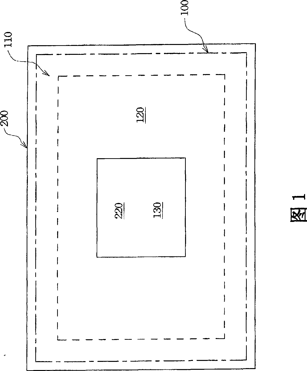
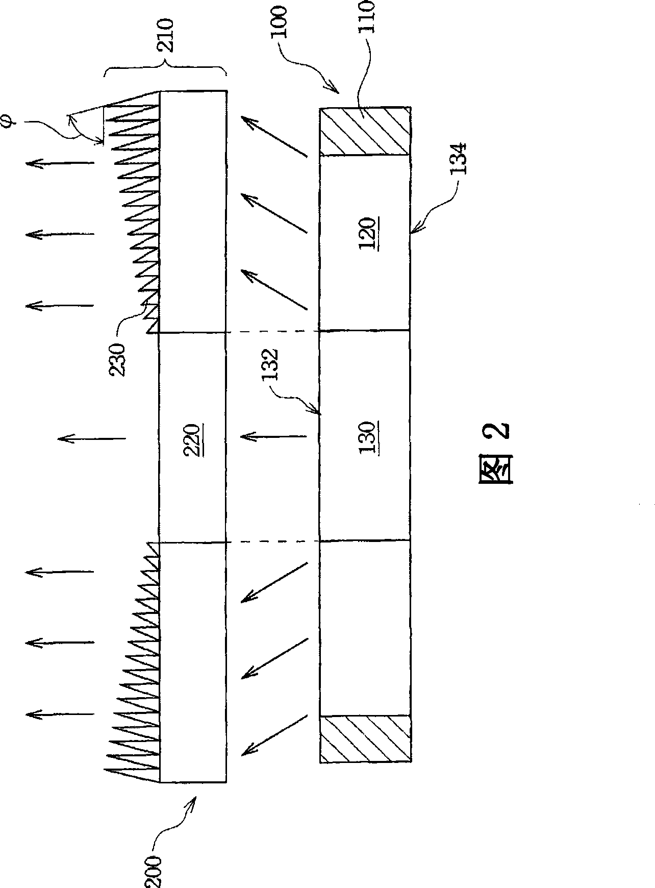
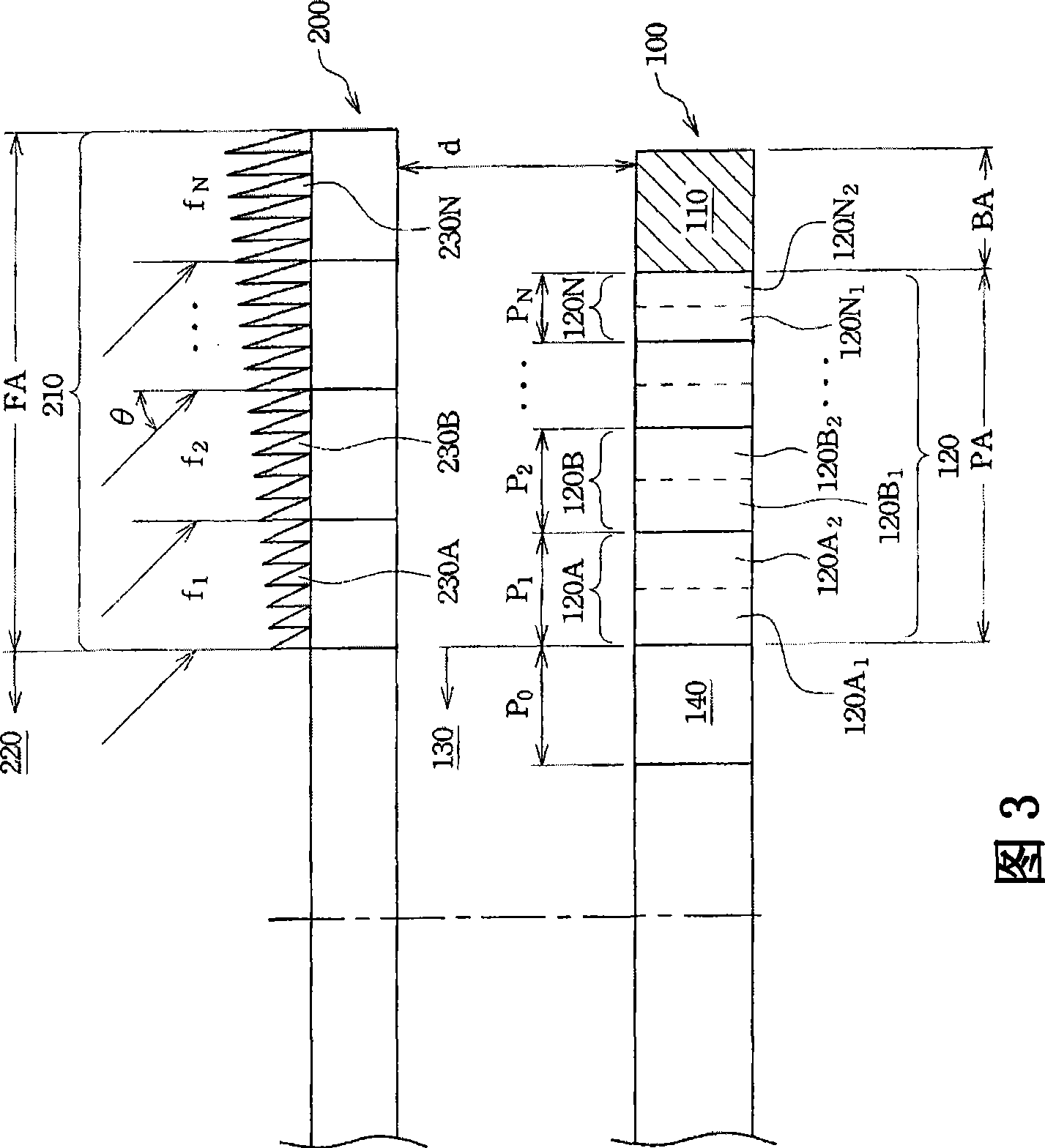
The invention provides a display device which comprises a display panel and a lens. The display panel is sequentially provided with a fixed pixel region, a shaded pixel region and a boundary region from center to edge, wherein the fixed pixel region is provided with a plurality of fixed pixels; the shaded pixel region is provided with a plurality of shaded pixel sets; and the width of the plurality of the shaded pixel sets is a first descending number sequence. The lens is provided with a shaded foci part and a flat part, wherein the flat part is arranged aligning to the fixed pixel region; the shaded foci part is arranged corresponding to the boundary region and the shaded pixel region; and the foci of the shaded foci part corresponding to the plurality of the shaded pixel sets is a second descending number sequence.
Description
technical field [0001] The present invention relates to a display device, in particular to a display device comprising a lens with a gradient focal length and a non-periodic pixel width. Background technique [0002] In the manufacturing process of liquid crystal display, due to factors such as the layout of the panel circuit circuit, frame glue and cutting tolerance, the peripheral frame of the liquid crystal display panel cannot display images, resulting in a circle of non-luminous border areas that cannot be eliminated, thus reducing the display panel. The area of the viewable area. In order to reduce the area of this non-luminous boundary area to increase the viewing area on the panel, the known technology is to arrange a magnifying lens or a circular Fresnel lens (Circular Fresnel Lens) above the liquid crystal display panel to directly perform two-dimensional The area is enlarged to generate a virtual image to shield the above-mentioned non-luminous border area. ...
Claims
Login to View More Application Information
Patent Timeline
 IPC IPC(8): G02F1/1335G02F1/133G09F9/35G09F9/30G02B3/08
Inventor高国峰陈政德程琮钦胡克龙周文彬李锡烈
OwnerAU OPTRONICS CORP