A power supply undervoltage protection circuit and a power supply including the protection circuit

A technology for protecting circuits and power supply undervoltage, which is applied in emergency protection circuit devices, protection for undervoltage or no voltage response, circuit devices, etc. , control module impact and other issues, to avoid frequent startup and shutdown, and to ensure reliability

Active Publication Date: 2011-12-14
VERTIV CORP
View PDF0 Cites 0 Cited by
  • Summary
  • Abstract
  • Description
  • Claims
  • Application Information

AI Technical Summary

Problems solved by technology

The existing power supply undervoltage protection circuit will cause frequent start-up and shutdown of the power switch tube, which will have a bad impact on the stress of the switch tube, the main power of the power supply, and the control module.

Method used


Image

  • A power supply undervoltage protection circuit and a power supply including the protection circuit
  • A power supply undervoltage protection circuit and a power supply including the protection circuit
  • A power supply undervoltage protection circuit and a power supply including the protection circuit

Examples


specific Embodiment approach 1

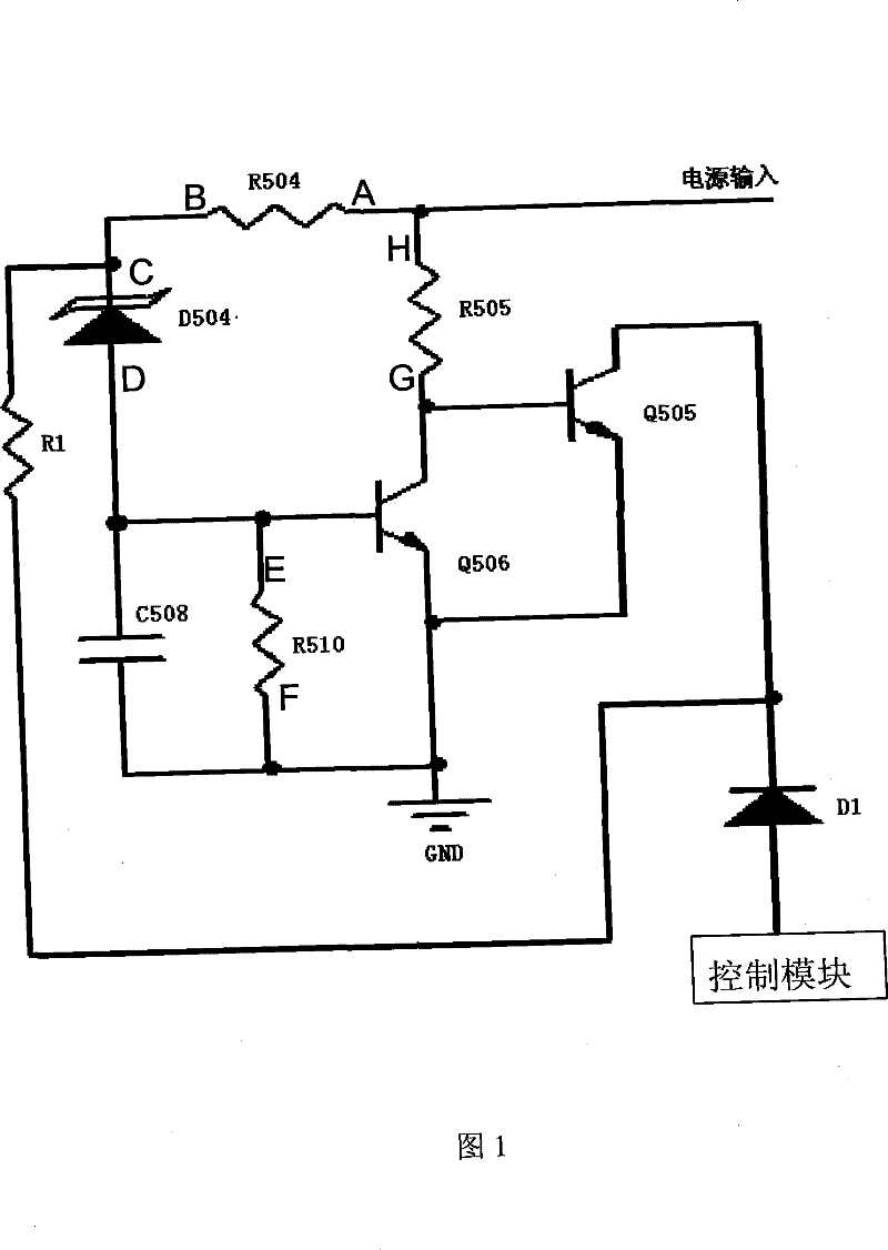
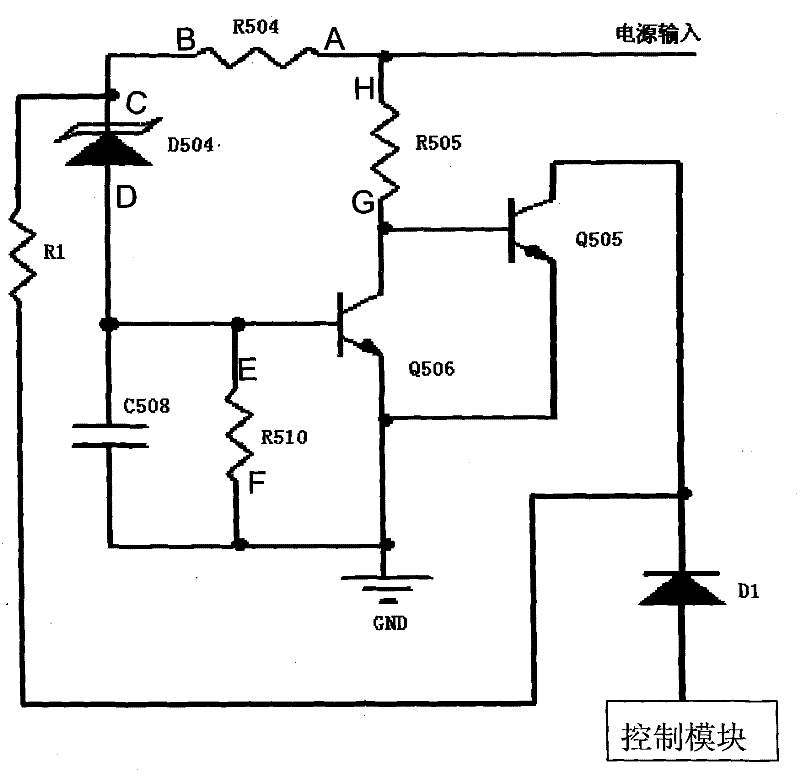
[0017] Such as figure 1 As shown, a power supply undervoltage protection circuit includes a sampling module 1, a comparison module 2 and a hysteresis protection module; the sampling module 1 is connected to the comparison module 2; the sampling module 1 collects the input voltage of the power supply and outputs it to the comparison module Module 2, the comparison module 2 compares the input voltage with the reference voltage and outputs a corresponding trigger signal to the control module when the input voltage is less than the reference voltage; the hysteresis protection module is connected to the output terminal of the sampling module and the control module between the module inputs. The hysteresis protection module includes a first resistance R1 and an isolation device, one end of the first resistance R1 is connected to the sampling module 1, the other end is connected to the output end of the comparison module 2, and one end of the isolation device is connected to the outp...

specific Embodiment approach 2

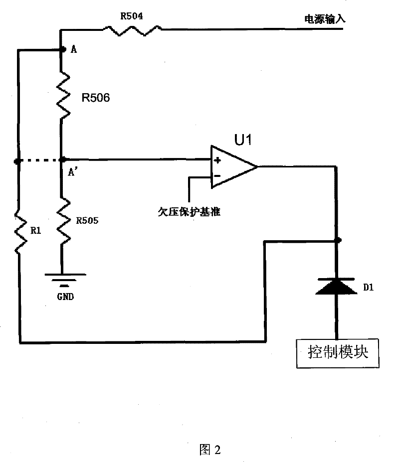
[0030] Such as figure 2 As shown, the difference between this specific embodiment and the first specific embodiment lies in the structures of the sampling module and the comparison module. In this specific embodiment, the sampling module includes a fourth resistor R504, a fifth resistor R505 and a sixth resistor R506, and the comparison module is composed of a comparator U1. The power input is grounded through the fourth resistor R504, the fifth resistor R505 and the sixth resistor R506. The positive input terminal of the comparator U1 is connected between the fifth resistor R505 and the sixth resistor R506, and the negative input terminal is connected with a reference voltage (namely: undervoltage protection reference)

[0031] One end of the first resistor R1 is connected to the sampling module 1 (that is, connected between the fourth resistor R504 and the sixth resistor R506; obviously, one end of the first resistor R1 can also be connected between the sixth resistor R506...


PUM


Abstract

The invention discloses a power supply undervoltage protection circuit and a power supply including the protection circuit. The undervoltage protection circuit includes a sampling module, a comparison module and a hysteresis protection module; the sampling module is connected with the comparison module; the sampling module collects the input voltage of the power supply And output to the comparison module, the comparison module compares the input voltage with the reference voltage and outputs a corresponding trigger signal to the control module when the input voltage is lower than the reference voltage; the hysteresis protection module is connected between the output terminal of the sampling module and the input terminal of the control module between. The power supply undervoltage protection circuit of the present invention includes a hysteresis protection module, and the hysteresis protection module will not immediately stop the undervoltage protection action when the undervoltage has just recovered at the undervoltage protection point after the undervoltage protection action The power supply is frequently started and shut down at the protection point to ensure the reliability of the power supply.

Description

technical field [0001] The invention relates to the field of power transformation, in particular to a power supply undervoltage protection circuit, and the invention also relates to a power supply including the undervoltage protection circuit. Background technique [0002] At present, various power supplies such as communication power supplies, electric operating power supplies, and industrial power supplies generally include a power supply undervoltage protection circuit. The power supply undervoltage protection circuit pulls down the voltage of the input terminal (comparison terminal) of the control module of the power supply when the input voltage of the power supply is lower than a certain value, and the control module will compare the voltage signal received from the comparison terminal with the triangular wave to generate a control The pulse of the switching tubes of the power supply (such as: switching tubes in the bridge rectifier circuit) turns off these switching t...

Claims


Application Information

Patent Timeline
Patent Type & Authority Patents(China)
IPC IPC(8): H02H3/24H02H7/10H02H3/26
Inventor 刘志宇赵辉向小路柳树渡
Owner VERTIV CORP
Why Eureka
Try Eureka