
Auxiliary converter fan speed regulation control circuit and method

An auxiliary converter, fan speed regulation technology, applied in the direction of engine control, excitation or armature current control, pump control, etc., can solve the cost and system complexity increase, can not achieve stepless speed regulation, multiple I/O resources and other issues, to achieve the effect of reducing noise and energy loss, occupying less control resources, and simple circuit structure

Active Publication Date: 2021-12-07
ZHUZHOU CSR TIMES ELECTRIC CO LTD
View PDF7 Cites 0 Cited by
  • Summary
  • Abstract
  • Description
  • Claims
  • Application Information

AI Technical Summary

Problems solved by technology

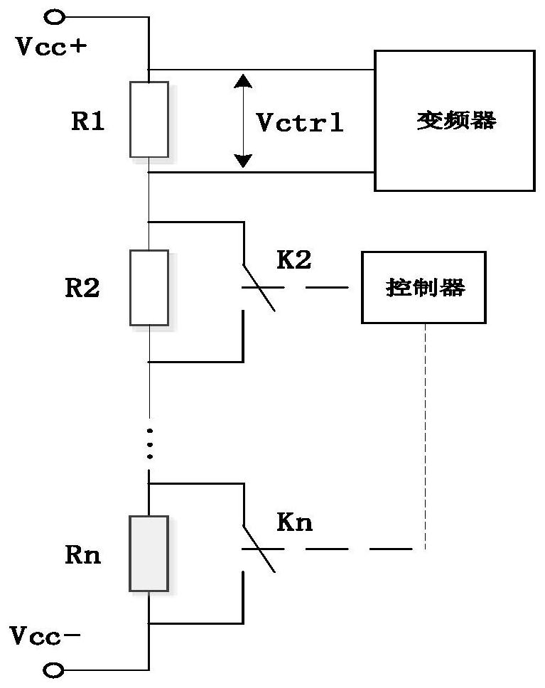
[0006] The principle of this solution is simple, but the speed of the fan can only be adjusted in stages, and stepless speed regulation cannot be realized; on the other hand, the more stages, the more resistors and relays are needed, the cost and system complexity increase, and the controller will also be occupied more I / O resources

Method used


Image

  • Auxiliary converter fan speed regulation control circuit and method
  • Auxiliary converter fan speed regulation control circuit and method
  • Auxiliary converter fan speed regulation control circuit and method

Examples


Embodiment Construction

[0043] The present invention is further described below with reference to the accompanying drawings and specific embodiments.

[0044] Such as Figure 4As shown, the auxiliary converter fan speed control circuit of the present embodiment includes a pulse generating unit 1 and a filter unit 2, and the output terminal of the pulse generating unit 1 is connected to the input of the filter unit 2; the pulse generating unit 1 is used to generate The duty cycle adjustable pulse signal, the filter unit 2 is used to filter an alternating current component of the pulse signal to obtain a DC voltage to act as a speed control signal of the auxiliary converter fan. The auxiliary converter fan speed control circuit of the present invention outputs a pulse signal by the pulse generating unit 1, and then converts the filter unit 2 into a DC voltage to serve as a speed control signal of the auxiliary converter fan; Since the duty cycle of the pulse signal is adjustable, the DC voltage output by th...


PUM


Abstract

The invention discloses an auxiliary converter fan speed regulation control circuit and method. The control circuit comprises a pulse generating unit and a filtering unit, wherein the output end of the pulse generating unit is connected with the input end of the filtering unit; the pulse generating unit is used for generating a pulse signal with an adjustable duty ratio; and the filtering unit is used for filtering an alternating current component of the pulse signal to obtain a direct current voltage which is used as a speed regulation signal of an auxiliary converter fan. The control method comprises the following steps that 1) the pulse generating unit generates a pulse signal with an adjustable duty ratio; and 2) the filtering unit filters an alternating current component of the pulse signal to obtain a direct current voltage which is used as a speed regulation signal of the auxiliary converter fan to regulate the speed of the auxiliary converter fan. The auxiliary converter fan speed regulation control circuit and method have the advantages of simple circuit structure, easiness in implementation, low cost, low energy consumption and the like, and a direct current voltage speed regulation signal is formed through the pulse signal.

Description

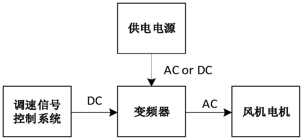
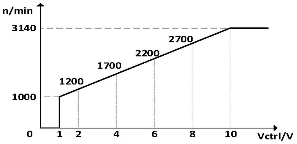
Technical field [0001] The present invention relates to the technical field of auxiliary converters, and more particularly to a conditial converter fan speed control circuit and a control method. Background technique [0002] The variable frequency fan in the auxiliary converter of the rail transit vehicle is usually composed of two major parts of the inverter and fan motor, and the power supply of the fan typically has three types of communication 3Ac380V and DC24V / 110V. The speed regulation signal of the fan is generally DC analog, by adjusting the level of the signal, changing the frequency of the frequency converter output voltage, thereby regulating the speed of the fan, the final control of the air, such as figure 1 Indicated. [0003] Among them, the speed control signal V ctrl The relationship with the speed N is like figure 2 Indicated. When the speed control signal level is less than 1V, the fan does not start; when the speed regulation signal changes from 1V to 10V, ...

Claims


Application Information

Patent Timeline
Patent Type & Authority Applications(China)
IPC IPC(8): F04D27/00H02P7/29
CPCF04D27/004H02P7/29F05D2270/303Y02B30/70
Inventor 陈思饶沛南杨奎施洪亮唐娟姚晨刘方华李碧钰谢伟
Owner ZHUZHOU CSR TIMES ELECTRIC CO LTD
Learn More