Organic light emitting device and method for manufacturing the same

一种有机发光器件、有机的技术,应用在电固体器件、电致发光光源、光源等方向,能够解决注入的电流量增加等问题,达到简化工艺、提高制备效率、缩短制备时间的效果

Active Publication Date: 2009-05-20
LG DISPLAY CO LTD
View PDF2 Cites 0 Cited by
  • Summary
  • Abstract
  • Description
  • Claims
  • Application Information

AI Technical Summary

Problems solved by technology

However, the amount of injected current is increased

Method used


Image

  • Organic light emitting device and method for manufacturing the same
  • Organic light emitting device and method for manufacturing the same
  • Organic light emitting device and method for manufacturing the same

Examples


Embodiment approach

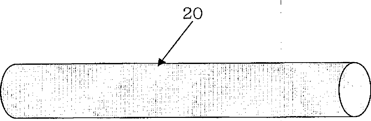
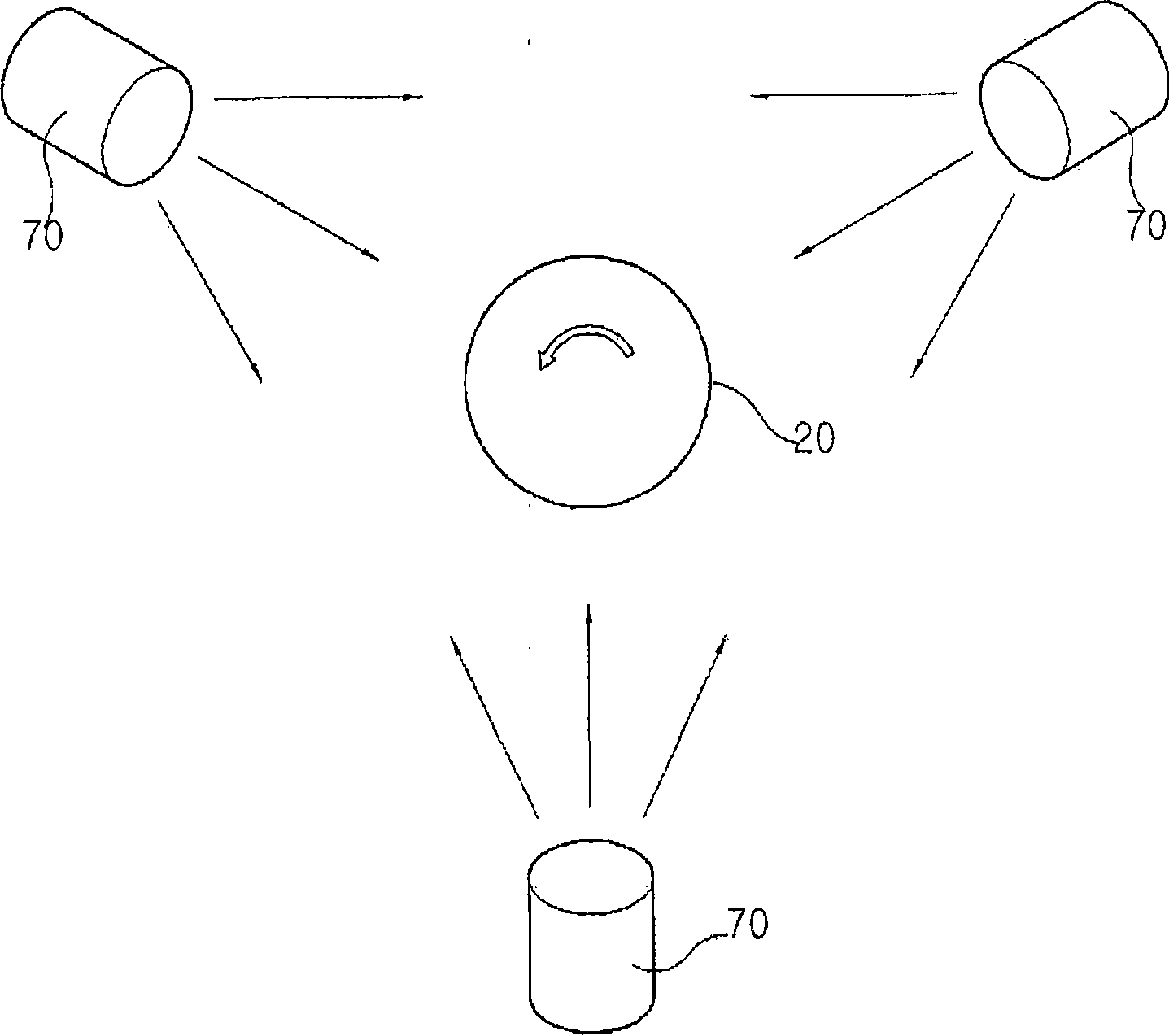
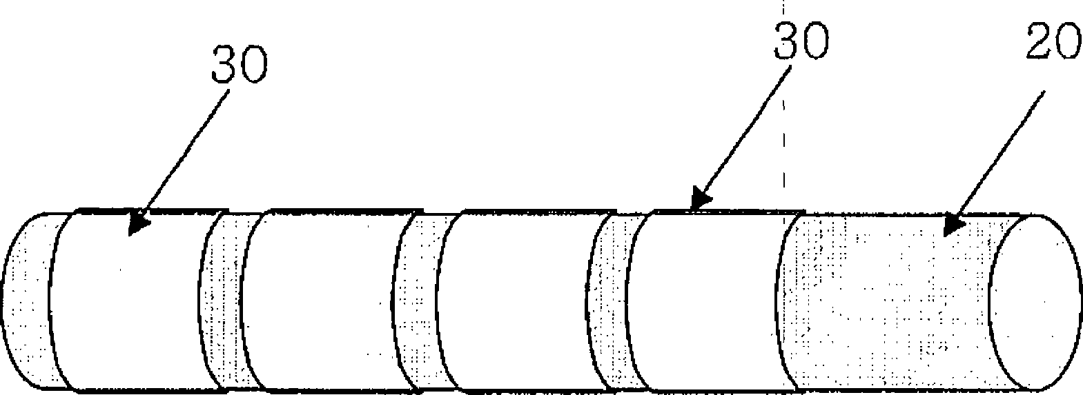
[0040] According to another embodiment of the present invention, a method for preparing an organic light-emitting device, the method includes the following steps: (a) preparing a base rod; forming a plurality of first electrodes; (c) forming a plurality of organic layers on the circumferential surfaces of the plurality of first electrodes at predetermined intervals along the longitudinal direction of the base rod; and (d) forming a plurality of organic layers at predetermined intervals along the longitudinal direction of the base rod; A plurality of second electrodes are formed on the circumferential surface of each organic layer, so that the second electrode of each organic light emitting unit is in contact with the first electrode of each organic light emitting unit adjacent to the first electrode of each organic light emitting unit, A plurality of organic light emitting units including the first electrode, the organic layer, and the second electrode formed on the organic lay...


PUM


Abstract

Disclosed is an organic light emitting device and a method of manufacturing the same. The organic light emitting device includes a base rod, and a plurality of organic light emitting units. Each of the plurality of organic light emitting units includes a first electrode formed on the base rod, an organic layer formed on the first electrode, and a second electrode formed on the organic layer. The plurality of organic light emitting units are formed in longitudinal direction of the base rod and come into continuous contact with each other. The first electrode of each of the organic light emitting units comes into contact with the second electrode of each of the organic light emitting units adjoining said first electrode of each of the organic light emitting units.

Description

technical field [0001] The invention relates to an organic light-emitting device comprising a plurality of organic light-emitting units in continuous contact with each other on a base rod and a preparation method thereof. [0002] This application claims priority from Korean Patent Application No. 10-2006-0040641 filed in KIPO on May 4, 2006, the entire disclosure of which is hereby incorporated by reference. Background technique [0003] Organic light-emitting devices using organic light-emitting devices are widely used in various lighting devices because of the advantages of obtaining high brightness using low voltage, and because of the advantages of low driving voltage, light weight and small size, wide viewing angle and fast response speed. It also applies to display devices. [0004] Organic light emission refers to the conversion of electrical energy into light energy by using organic substances. That is, when an organic layer is provided between an anode and a cath...

Claims


Application Information

Patent Timeline
Patent Type & Authority Applications(China)
IPC IPC(8): H05B33/22
CPCH01L27/3204H01L51/5287H10K59/86H10K50/182H05B33/22H05B33/26H05B33/10
Inventor 崔贤孙世焕
Owner LG DISPLAY CO LTD
Why Eureka
Try Eureka