Elevator control system

An elevator control, elevator technology, applied in elevators, transportation and packaging, etc., can solve problems such as increasing deceleration, increasing capacity, and spending a lot of time

Active Publication Date: 2009-05-27
HITACHI LTD
View PDF3 Cites 13 Cited by
  • Summary
  • Abstract
  • Description
  • Claims
  • Application Information

AI Technical Summary

Problems solved by technology

However, this forced deceleration operation is aimed at the overspeed that occurs when decelerating in normal operation, and its purpose is to increase the deceleration so that the elevator car stops at the highest floor or the lowest floor parking position. Patent documents 1 and 2 The technology in is not a technology for maintenance ope...

Method used


Image

  • Elevator control system
  • Elevator control system
  • Elevator control system

Examples


Embodiment 1

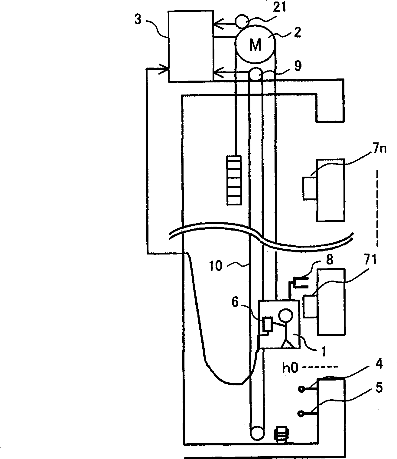
[0034] figure 1 It is a schematic diagram of the control system of the elevator in the first embodiment of the present invention. As shown in the drawing, a hoist 2 including a drive motor for raising and lowering the elevator car 1, and a control device 3 for controlling the drive of the hoist 2 are provided. Normally, the speed control of the drive motor is performed by comparing the speed command of the elevator with the output of the rotary encoder 21 for detecting the rotational speed of the hoist 2 .

[0035] As a safety device of the elevator terminal floor, a limit switch 4 outputting a stop command for limiting the descent of the elevator car 1 and a final limit switch 5 arranged below the limit switch 4 are provided.

[0036] For maintenance operation, a connector is provided inside the elevator car 1, to which the controller 6 can be connected and also detached. When performing maintenance operation, after the maintenance personnel connect the controller 6 to the ...

Embodiment 2

[0053] Figure 7 is a processing flowchart of the second embodiment of the present invention. The focus of the second embodiment is the final limit switch 5 . Usually, the final limit switch 5 is a safety device provided in order to deal with the situation that the elevator car greatly exceeds the parking position due to a major failure during normal operation. Therefore, when the final limit switch 5 is set to act on it, the power supply to the main circuit of the power conversion device is cut off to stop the power supply to the winch, and it is forbidden to restart and reset in an automatic operation mode.

[0054] The second embodiment is when the elevator with high lift descends and stops towards the bottom floor during maintenance operation, although the first embodiment is adopted, unfortunately it is still a safety measure when the final limit switch 5 is actuated.

[0055] First, in step 71, when the operation of the final limit switch 5 is detected, in step 72, the...

Embodiment 3

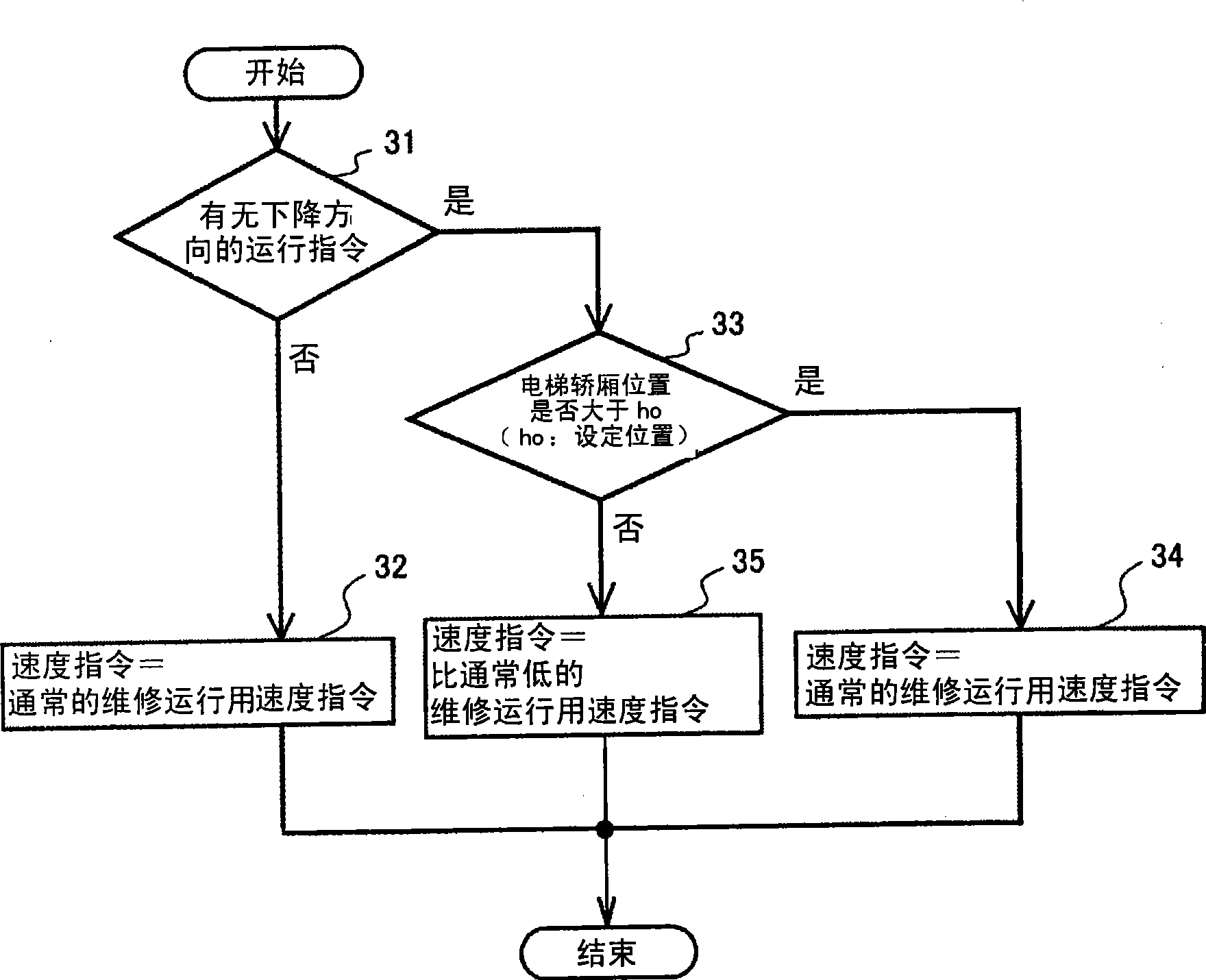
[0058] Figure 8 is a processing flowchart of the third embodiment of the present invention. The focus of the third embodiment is story height measurement. The floor height measurement is an operation performed to store the elevation value of each floor from the standard floor in the built-in storage device of the control device 3 .

[0059] For example, if figure 1 As shown, the elevator car 1 is raised from the standard floor (for example, the bottom limit switch), and the position detector 8 detects the number of pulses when passing through the shielding plates 71-7n, thereby grasping the parking position of each floor. In this way, the floor height values ​​of the shielding panels 71 - 7n of all floors up to the highest floor are stored. Usually, floor height measurement is performed at the time of commissioning before building completion, and the operation of the elevator car 1 at this time is performed at a low speed as in the low-speed operation of the first embodime...


PUM

PropertyMeasurementUnit
Lengthaaaaaaaaaa

Abstract

The invention provides an elevator control system associated with maintaining operation of a high-lift elevator, capable of well exerting stopping action near the bottom layer and high-layer testing operation according to the elevator control system. In the maintaining operation of a high-lift elevator, the maintaining operation speed (low-speed operation speed) is reduced from current 30m every minute to 15m every minute when it drops toward the bottom layer and when the elevator carrier exceeds the bottom layer to reach a limit switch (4). According to a preferable exertion mode of the invention, a final limit switch (5) may be prevented from action caused by damped oscillation of the elevator carrier via ladder variable of a speed indication and the maintaining time may be shortened when the high-lift elevator is in maintenance.

Description

technical field [0001] The invention relates to an elevator control system, in particular to an elevator control system which improves the maintenance and operation of high-lift elevators in super high-rise buildings. Background technique [0002] In conventional elevator maintenance operations, the operator operates a controller around him to raise and lower the elevator car. The driving speed during maintenance operation is a relatively low constant speed of about 15m / min to 30m / min, which is very low compared to the rated speed during normal operation, but its characteristic is that it can be operated by operating the controller. The elevator stops at an arbitrary place such as a floor and an intermediate portion between floors. Hereinafter, the driving speed during the maintenance operation is referred to as a low-speed operation speed. [0003] On the other hand, in addition to the deceleration during the maintenance operation, the elevator device disclosed in Patent ...

Claims


Application Information

Patent Timeline
IPC IPC(8): B66B5/10B66B5/06B66B5/02
Inventor 三田史明岸川孝生大沼直人迫田友治蛭田清玄保立尚史稻叶博美绫野秀树森和久
Owner HITACHI LTD
Why Eureka
Try Eureka