Vacuum prepressing ground treatment water drainage structure by sand furrow method

A foundation treatment and drainage structure technology, which is applied in infrastructure engineering, soil protection, construction, etc., can solve problems such as the shortage of medium and coarse sand resources, the cost and duration of vacuum preloading method, and the high price. Short, low cost, and the effect of reducing loss along the way

Inactive Publication Date: 2009-05-27
CHINA COMM CONSTR FIRST HARBOR CONSULTANTS
View PDF0 Cites 3 Cited by
  • Summary
  • Abstract
  • Description
  • Claims
  • Application Information

AI Technical Summary

Problems solved by technology

The horizontal drainage and vacuum transmission system of the vacuum preloading method is composed of sand cushions and filter pipes. At present, due to the shortage of medium and coarse sand resources and high prices, it has a great impact on the cost and construction period of the vacuum preloading method.

Method used


Image

  • Vacuum prepressing ground treatment water drainage structure by sand furrow method
  • Vacuum prepressing ground treatment water drainage structure by sand furrow method

Examples


Embodiment Construction

[0013] The application of the drainage structure of the sand ditch method vacuum preloading foundation treatment of the present invention will be further described below in conjunction with the accompanying drawings.

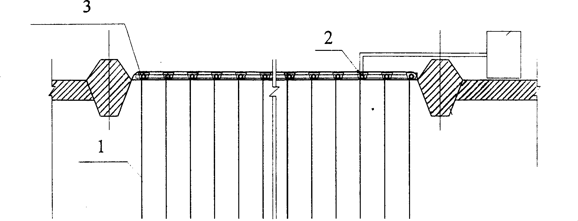
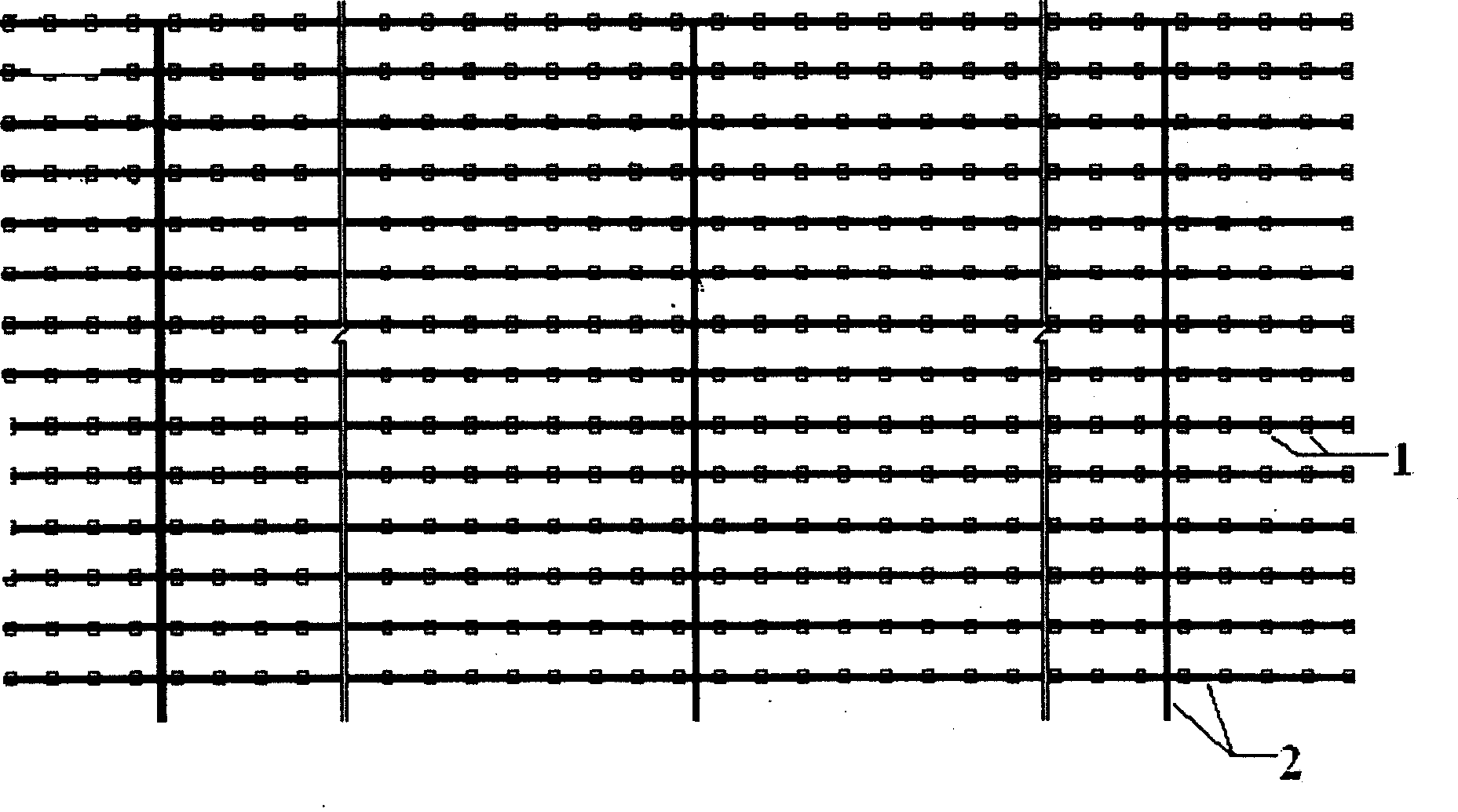
[0014] Such as figure 1 , 2 As shown, the drainage structure of the vacuum preloading method foundation treatment of the present invention: the structure includes a drainage system and a sealed vacuum system, the drainage system includes a plastic drainage board 1 embedded in the soil, and drains water along the top of the plastic drainage board. A sand ditch 3 is arranged in the soil body of the board head parallel to the plastic drainage board, and the drainage board head of the plastic drainage board is directly connected to the filter pipe 2, and the filter pipe 2 is embedded in the sand ditch 3.

[0015] The cross-sectional shape of the sand ditch 3 is one of trapezoidal, rectangular, U-shaped and a combination of trapezoidal, rectangular, U-shaped. The s...


PUM


Abstract

The invention provides a drainage structure for use during sand-drain vacuum preloaded ground treatment. The structure comprises a drainage system and a sealing and vacuumizing system, wherein the drainage system comprises a plastic draining board buried in a soil body. A sand drain is arranged in the soil body along the draining board head on the upper part of the plastic draining board and parallel to the plastic draining board. The draining board head of the plastic draining board is directly connected with a filter tube. The filter tube is buried in the sand drain. The cross section of the sand drain can be in a trapeziform shape, rectangular shape, U-shape or a combined shape of the trapeziform shape, the rectangular shape and the U-shape. The sand in the sand drain can be fine sand, medium sand, coarse sand, gravelly sand or a mixture of the fine sand, the medium sand, the coarse sand and the gravelly sand. The drainage structure reduces loss of the vacuum degree during transmission, increases a vacuum preloaded horizontal drainage channel through a sand drain structure, and has the advantages of low cost, less limitation from the sand source of the coarse sand and low construction period compared with the prior vacuum preloading method.

Description

technical field [0001] The invention relates to the foundation treatment technology in the field of civil engineering construction, especially the drainage structure of the sand trench method vacuum preloading foundation treatment, which is suitable for the construction field of silt and muddy soil using the preloading drainage consolidation method, and is suitable for those lacking medium and coarse sand resources. Regional applications are of particular significance. Background technique [0002] Since the traditional vacuum preloading method was successfully applied in the late 1980s, a large number of engineering practices have proved that it is an effective method for strengthening soft soils, such as silt and silty soils. It is still the main foundation treatment technology for soft soil foundations. The horizontal drainage and vacuum transmission system of the vacuum preloading method is composed of sand cushions and filter pipes. At present, due to the shortage of me...

Claims


Application Information

Patent Timeline
Patent Type & Authority Applications(China)
IPC IPC(8): E02D3/10
Inventor 唐元松王克勤蔡波刘宏伟李学艳陈占锋尹广田朱子平周宝江
Owner CHINA COMM CONSTR FIRST HARBOR CONSULTANTS
Why Eureka
Try Eureka