Source container of a VPE reactor

A container and reactive gas technology, which is applied in the directions from chemical reactive gas, chemical instruments and methods, gaseous chemical plating, etc., can solve the problems of source conversion efficiency change and inconstancy, etc.

Inactive Publication Date: 2009-05-27
AIXTRON AG
View PDF3 Cites 2 Cited by
  • Summary
  • Abstract
  • Description
  • Claims
  • Application Information

AI Technical Summary

Problems solved by technology

This results in a change in the conversion efficiency of the source
Specifically, this inconstant source conversion is disadvantageous in the case of small surfaces that cannot be avoided when the fluid passes vertically through the source region

Method used


Image

  • Source container of a VPE reactor
  • Source container of a VPE reactor
  • Source container of a VPE reactor

Examples


Embodiment Construction

[0021] The VPE reactor represented in Figure 4 is a horizontal reactor, since the process chamber 21 extends in the horizontal direction. The floor of the substantially circular process chamber 21 forms a base 23 . The soleplate is heated from below by means of resistive heaters 25 . Other types of heating are also possible; in particular, RF heating may be employed. On a disk-shaped bottom plate 23, there are a large number of substrates 22. The substrate 22 is arranged around the center of the base 23 in a circular arrangement.

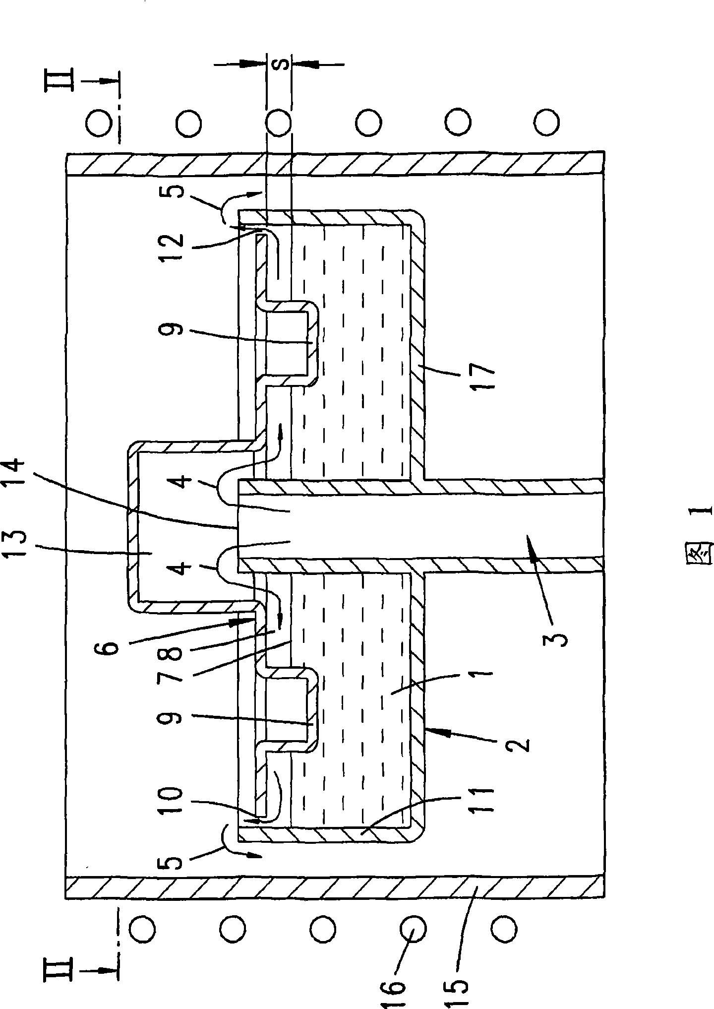
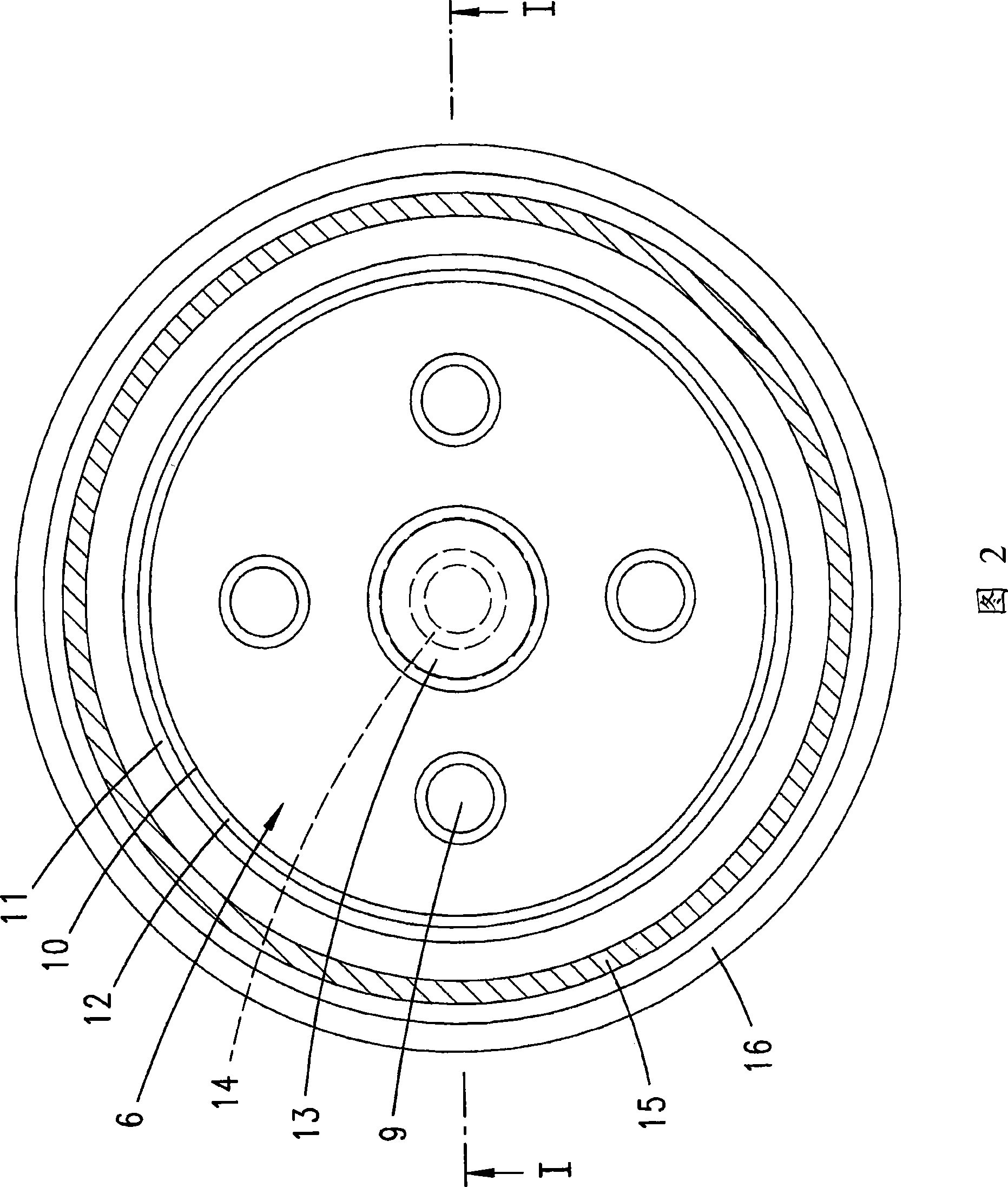
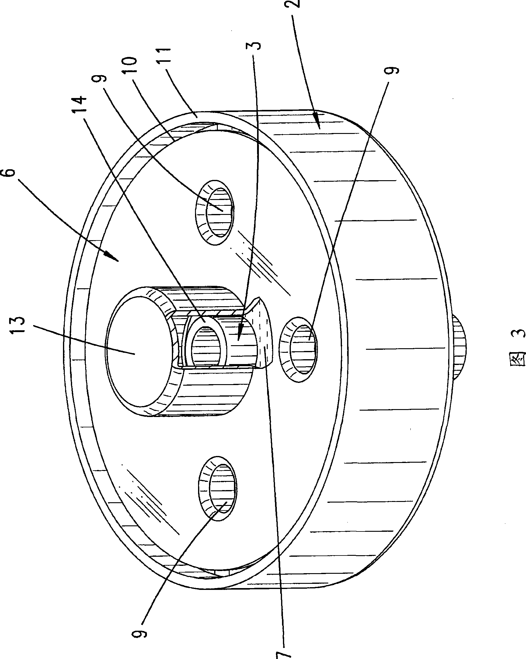
[0022] Above the base 23 is a process chamber ceiling 24 . It extends parallel to the bottom plate 23 and has an opening in the center. The opening is located outside the area on the base 23 where the substrate 22 is placed. Above this circular opening in the process chamber ceiling 24 is the source region. The source region includes ducts extending in a vertical direction. The duct forms the wall 15 of the source region. The tube is closed ...


PUM


Abstract

The invention relates to a source arrangement of a VPE deposition device, comprising a container (2) containing a liquid or solid starting material (1) and having a top opening, a feed line (3) for a reactive gas (4) which reacts with the starting material (1) in order to produce a process gas (5) that contains the starting material. The aim of the invention is to temporally stabilize the source reaction. For this purpose, a cover (6) rests directly on the starting material (1) and defines a volume (8) between the cover and the surface (7) of the starting material (1), the reactive gas (4) flowing through said volume and the feed line (3) running into it.

Description

technical field [0001] The invention relates to a source arrangement (arrangement) of a VPE deposition apparatus comprising: a container (2) containing a liquid or solid starting material (1) and having an opening at the top; a supply line (3) for a reaction gas (4), the said reaction gas (4) reacts with the starting material (1) to produce a process gas (5) containing the starting material; and a lid placed directly on the starting material (1). [0002] Furthermore, the invention relates to a VPE deposition apparatus comprising a process chamber and a source zone arranged upstream in the flow direction of the process gas, in which source zone there is a supply line for the reaction gas and contains a liquid or solid starting material and has a top open container. Background technique [0003] A device of a general type is known from DE 3801147 A1. Among them, the powder filling is located on the porous wall. The perforated plate sits on the powder fill. The upper perfo...

Claims


Application Information

Patent Timeline
Patent Type & Authority Applications(China)
IPC IPC(8): C30B25/14C23C16/458
CPCC23C16/4488C30B25/14C23C16/458
Inventor 沃尔特·弗兰肯约翰尼斯·卡普勒
Owner AIXTRON AG
Why Eureka
Try Eureka