
A three-stage surface plasmon lens

A surface plasmon, three-stage technology, applied in the field of ion polariton, can solve the problems of not fully utilizing the circular grating structure, inconvenient practical application, and low excitation efficiency of surface plasmon polariton, so as to avoid alignment Problems, Optimizing Size, Effects of Increasing Numerical Aperture

Active Publication Date: 2017-10-17
XIAMEN UNIV
View PDF3 Cites 0 Cited by
  • Summary
  • Abstract
  • Description
  • Claims
  • Application Information

AI Technical Summary

Problems solved by technology

When linearly polarized light is used as the excitation source, the entire circular grating structure is not fully utilized, especially at the position where the polarization direction is parallel to the arc tangent, and the excitation efficiency of surface plasmons is very low (A.V.Zayatsa, I.I. Smolyaninovb, and A.A. Maradudinc, "Nano-optics of surface plasmon polaritons", Phys. Reports 408, 131 (2005))
However, there are two major problems in the scheme of radially polarized excitation: firstly, linearly polarized light needs to be processed in advance to generate radially polarized light, which brings inconvenience to practical applications; secondly, radially polarized illumination has alignment problems between the light source and the structure , that is, it is necessary to ensure that the center of the excitation spot is on the center of the circular lens

Method used


Image

  • A three-stage surface plasmon lens
  • A three-stage surface plasmon lens
  • A three-stage surface plasmon lens

Examples


Embodiment Construction

[0022] The following embodiments will further illustrate the present invention in conjunction with the accompanying drawings.

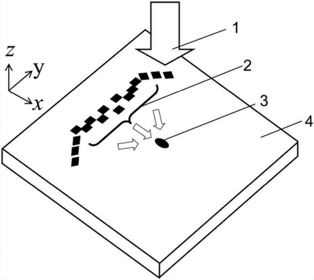
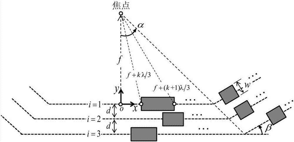
[0023] see figure 1 , the present invention consists of three layers of rectangular grooves 2 etched on the metal surface 4, under the illumination of linearly polarized light 1 incident perpendicular to the metal surface 4, a smaller-sized surface plasmon focus 3 that breaks through the diffraction limit will be formed , the width W of the rectangular groove 2 is λ / 2, where λ is the wavelength of the surface plasmon (see figure 2 ), the central position of each layer of grooves is distributed on three line segments, for the i-th layer (i=1,2,3), its trajectory is given by the following piecewise function:

[0024]

[0025] Among them, f is the focal length, d=2λ / 3 is the layer spacing of the horizontal line segment, α and β are two parameters that need to be optimized, and their meanings can be found in figure 2 . The signs "+" and "-" in fo...


PUM


Abstract

The invention discloses a three-section surface plasmon polariton lens, and relates to a surface plasmon polariton. The lens is formed by three layers of rectangular grooves etched on the surface of a metal, a small-size surface plasmon polariton focus breaking through the diffraction limit is formed under the illumination of linearly polarized light, the width of the grooves is lambda / 2, the center positions of each layer of grooves are distributed on three line segments, and for the i layer (i=1, 2, 3), the length and the center position of each layer of grooves are designed as follows: the distances from the midpoints of the left and right sides of the i layer of grooves to the focus separately satisfy f+(i-1)d+k lambda / 3 and f+(i-1)d+(k+1) lambda / 3, wherein k is the level of a groove, namely the k difference of two adjacent grooves on the same layer is 3, and each groove corresponds to a Fresnel zone in the traditional zone plate; and when the plane wave polarizing in the y direction is perpendicular to the illumination structure on the surface of the metal, the surface plasmon polaritons are excited by the same phase on each grove, and constructively interfere with one another when being propagated to a focus to form the focus.

Description

technical field [0001] The invention relates to surface plasmons, in particular to a three-stage surface plasmon lens capable of realizing ultra-small focus. Background technique [0002] Surface Plasmon Polariton (Surface Plasmon Polariton) is an electromagnetic field surface mode localized on the metal / medium surface, which is characterized by the exponential decay of the electromagnetic field strength in the direction perpendicular to the metal surface; Wavenumbers propagate along the metal surface. Under certain conditions, energy conversion between light and surface plasmons can be achieved. This allows people to use surface plasmons to manipulate light in the range of micrometer and nanoscale. Research on various functional devices based on surface plasmons and related theoretical research has become a hot spot in recent years, attracting the attention of many researchers. [0003] Among the many planar photonic devices of surface plasmons, the research on the lens ...

Claims


Application Information

Patent Timeline
Patent Type & Authority Patents(China)
IPC IPC(8): G02B5/00G02B27/00
CPCG02B5/008G02B27/0012
Inventor 王家园
Owner XIAMEN UNIV
Learn More