Veneer mounting structure

A technology for installing structures and decorative panels, which is applied in building components, building structures, buildings, etc., can solve the problems that the installation direction of decorative panels is difficult to match the actual working conditions and the cost of decoration increases.

Pending Publication Date: 2021-07-06
ZHEJIANG YASHA DECORATION
View PDF0 Cites 0 Cited by
  • Summary
  • Abstract
  • Description
  • Claims
  • Application Information

AI Technical Summary

Problems solved by technology

However, under different decoration conditions, the installation direction of the decorative panel is different. The above-mentioned installation method may easily cause the installation d

Method used


Image

  • Veneer mounting structure
  • Veneer mounting structure

Examples


Example Embodiment

[0023] Example:

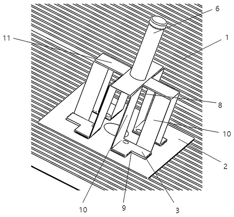
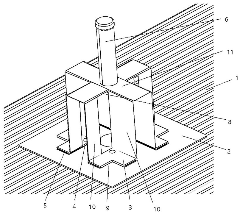
[0024] see Figure 1-2 , This embodiment provides a veneer installation structure, including a veneer 1, a mounting plate 2 and a hanging piece.

[0025] The decorative panel 1 is set horizontally, the mounting plate 2 is fixed on the upper surface of the decorative panel 1 by screws, the upper surface of the mounting plate 2 is provided with a connecting seat, the lifting piece is connected with the connecting seat, the upper end of the lifting piece is installed on the ceiling, and the lifting piece passes through The connecting seat hoistes the mounting plate 2 and the decorative panel 1 .

[0026] Specifically, the number of connecting seats is at least three, all connecting seats are arranged in a circular array, and the distance between two circumferentially adjacent connecting seats in the circular array is a constant value, and the hoisting parts are connected with all connecting seats in the circular array. Detachable connection.

[0027] Taking t...


PUM


Abstract

The invention discloses a veneer mounting structure. The veneer mounting structure comprises a veneer, a mounting plate and a hoisting part, the mounting plate is fixed to the upper surface of the veneer, three or more connecting seats are arranged on the upper surface of the mounting plate, all the connecting seats are arranged in an annular array, the distance between every two circumferentially adjacent connecting seats is a fixed value, and the hoisting piece is detachably connected with the connecting seats so that hoisting can be carried out on the veneer through the mounting plate. The hoisting piece is connected with the mounting plate through the connecting seats so that hoisting can be carried out on the veneer through the mounting plate; and the structures of all the connecting seats are the same, the annular array has rotational symmetry, that is, every time the veneer drives the mounting plate to rotate by a specific angle, the structure of the annular array of the whole connecting seats is substantially unchanged in spatial distribution, and therefore, the hoisting piece can be connected with all the connecting seats under the condition that the annular array is located at the specific angles, and the corresponding veneer can further be hoisted by the hoisting piece.

Description

technical field [0001] The invention relates to a decorative panel installation structure, which belongs to the field of decorative panel installation. Background technique [0002] Ribs are installed on the top surface of traditional decorative panels, and the ribs are connected to the keel on the ceiling. The ceiling relies on the keel to lift the decorative panel, and the installation direction of the corresponding decorative panel is subject to the installation direction of the keel. However, under different decoration conditions, the installation direction of the decorative panel is different. The above-mentioned installation method will easily make the installation direction of the decorative panel difficult to match the actual working conditions, and the decorative panel has to be processed twice, resulting in an increase in decoration costs. Contents of the invention [0003] The technical problem to be solved by the present invention is to overcome the deficiencie...

Claims


Application Information

Patent Timeline
IPC IPC(8): E04B9/00E04B9/18E04B9/22E04B9/04
CPCE04B9/00E04B9/18E04B9/22
Inventor 丁欣欣丁泽成周东珊王聪聪钱依玲张烁培
Owner ZHEJIANG YASHA DECORATION
Why Eureka
Try Eureka