Eureka AIR delivers breakthrough ideas for toughest innovation challenges, trusted by R&D personnel around the world.

Bead ring locking mechanism of tire vulcanizer

A technology of tire vulcanization and wire ring, which is applied to tires, other household appliances, household appliances, etc. It can solve the problems of looseness and insufficient tightening of positioning screws 53, and achieve the effect of simple replacement and reliable rotation

Inactive Publication Date: 2009-06-03
MITSUBISHI HEAVY IND LTD
View PDF0 Cites 2 Cited by
  • Summary
  • Abstract
  • Description
  • Claims
  • Application Information

AI Technical Summary

Problems solved by technology

After repeated operations like this, the screwing of the positioning screw 53 to the mounting hole 52 will gradually become loose, and the traveler 51 will rotate relative to the elevator 50 during the replacement operation of the lower traveler 51, so it is necessary to frequently check or replace the lower traveler 51
[0006] In addition, since the tip of the set screw 53 on the side of the lower traveler 51 is in point contact with the outer peripheral surface of the lifter 50, the tightening of the set screw 53 is insufficient, and the same problem as above occurs.

Method used


Image

  • Bead ring locking mechanism of tire vulcanizer
  • Bead ring locking mechanism of tire vulcanizer
  • Bead ring locking mechanism of tire vulcanizer

Examples


Embodiment Construction

[0030] Below, according to Figure 1 to Figure 6 Embodiments of the present invention will be described.

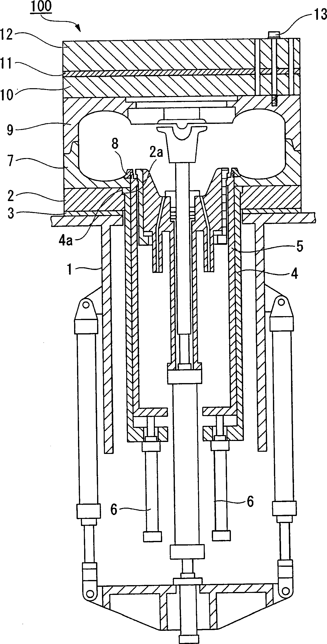
[0031] figure 1 It is a front sectional view showing the whole of the vulcanizing machine 100 . A lower deck 2 is fixed to the upper surface of the base 1 with bolts (not shown) via a heat insulator 3 . In addition, a central mechanism outer cylinder 4 is arranged at the center of the base 1 , and its upper end is inserted into the center hole of the lower deck 2 , and the upper flange 4 a is engaged with the upper inner surface 2 a of the lower deck 2 . In addition, a cylindrical elevator 5 is slidably inserted into the inner peripheral surface of the center mechanism outer cylinder 4 . The elevator 5 is raised and lowered by a cylinder 6 disposed under the center mechanism outer cylinder 4 .

[0032] A lower mold 7 is provided on the lower platen 2 . A lower traveler 8 functioning as a part of the die is engaged with the inner periphery of the lower die 7 . The l...


PUM


Abstract

The invention relates to a bead ring locking mechanism, which restricts the relative turning of a tubular lifter moved upward or downward on the outside of a central mechanism outer casing with respect to an annular bead ring attached to the outer circumference of the lifter to form a part of a die. The locking mechanism includes a stopper member installed at the bead ring and attached so as to move back and forth with respect to the lifter, and an actuating member which moves the stopper member from the bead ring to the lifter. A recessed portion is formed at the lifter, a raised portion is formed at the stopper member, and the raised portion is fitted into the recessed portion by pressing the stopper member to the lifter using the actuating member.

Description

technical field [0001] The present invention relates to a tire vulcanizing machine, and more particularly, to a bead ring stop mechanism for restricting the rotation of the bead ring relative to the elevator. Background technique [0002] For example, the tire vulcanizing machine disclosed in JP-A-11-114965 has: a base for fixing the mold via a platen, a central mechanism outer cylinder fixed on the base, and a central mechanism outer cylinder arranged inside the central mechanism outer cylinder. An elevator for raising and lowering the lower cylinder, and a bead ring attached to the upper end of the elevator to form a part of the mold. In this tire vulcanizing machine, tires are vulcanized within the mold. [0003] A bayonet mechanism for engaging with the lift is provided at the upper end of the lift. The pin mechanism engages the traveler in the axial direction with the elevator, and when the elevator is raised, the traveler is rotated in the circumferential direction t...

Claims


Application Information

Patent Timeline
IPC IPC(8): B29C35/02B29L30/00
CPCB29D30/0662B29D30/0601B29C35/02B29D30/08B29D30/26
Inventor 登本圭一
Owner MITSUBISHI HEAVY IND LTD
Why Eureka
Eureka Blog
Learn More