Solid-liquid separation device

A solid-liquid separation and separation part technology, applied in the field of solid-liquid separation devices, can solve problems such as shortening the life of the movable plate, and achieve the effect of inhibiting wear

A solid-liquid separation and separation part technology, applied in the field of solid-liquid separation devices, can solve problems such as shortening the life of the movable plate, and achieve the effect of inhibiting wear

CN101448557AInactive Publication Date: 2009-06-03AMCON FUJIAN ENVIRONMENT PROTECTION EQUIP CO LTD

Image

  • Solid-liquid separation device
  • Solid-liquid separation device
  • Solid-liquid separation device

Examples


Embodiment Construction

[0066] Hereinafter, embodiments of the present invention will be described with reference to the drawings, and the aforementioned conventional disadvantages will be more specifically described with reference to the drawings.

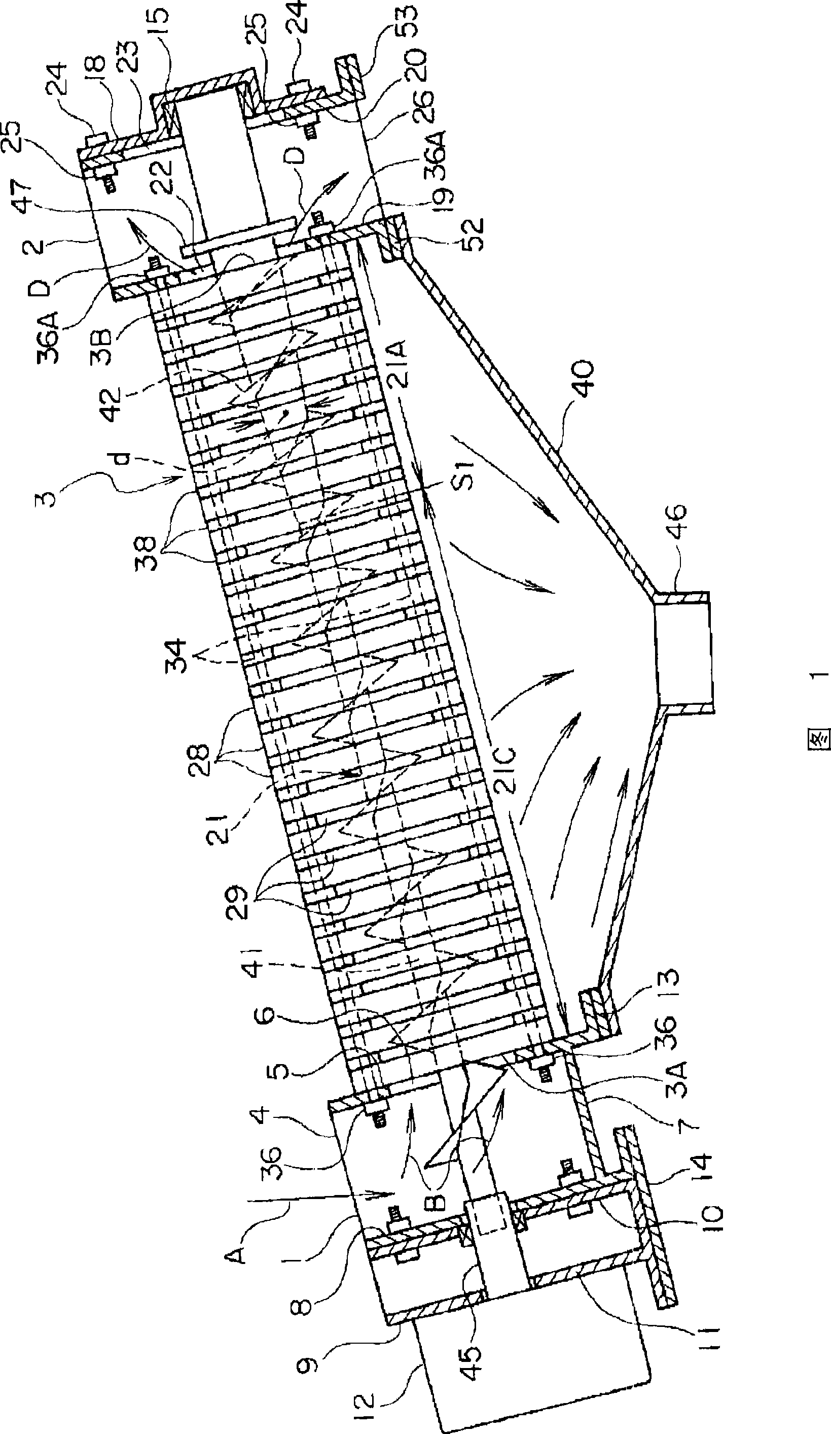
[0067] Fig. 1 is a sectional front view showing an example of a solid-liquid separator. This solid-liquid separator can also separate solid components and liquid components from various treatment objects containing oil and other liquids other than water. Here, the case of dehydrating sludge containing a large amount of water will be described.

[0068] The solid-liquid separation device shown in FIG. 1 has an inlet member 1, an outlet member 2, and a solid-liquid separator 3 disposed therebetween. The inlet member 1 is formed in the shape of a rectangular box with an upper opening, and constitutes an inflow port 4 through which sludge flows through the upper opening. Reference numeral 7 denotes the bottom wall of the inlet part 1 . In addition, an open...


PUM


Abstract

The present invention relates to a solid-liquid separation device having a solid-liquid separation section provided with adjacent stationary plates and movable plates arranged between the adjacent stationary plates and also having at least one screw extending so as to penetrate the solid-liquid separation section. The movable plates are formed such that they are pushed and moved by the screw that rotates.An object to be processed having entered in the solid-liquid separation section is moved toward the exit of the solid-liquid separation section, and at the same time, filtrate separated from the object is discharged to the outside through a filtrate discharge gap of the solid-liquid separation section. Wear of the movable plates are suppressed with dewatering efficiency for slurry maintained at a high level. The diameter (d) of the shaft (41) of a screw section (21A) on the exit side of the solid-liquid separation section (3) gradually increases from a predetermined position (S1) of the screw in the solid-liquid separation section (3) toward the exit side, and the lead angle of the screw section (21A) is set to the range from 10 DEG to 30 DEG.

Description

technical field [0001] The present invention relates to a solid-liquid separation device, comprising a solid-liquid separation unit having a plurality of adjacent fixed plates and a plurality of movable plates arranged between the adjacent fixed plates, and a solid-liquid separation unit penetrating through the solid-liquid separation unit. Extending at least one screw, the movable plate is formed so that the rotating screw pushes the movable plate, and the object to be treated entering the solid-liquid separation part moves toward the outlet of the solid-liquid separation part by the rotating screw , while the filtrate separated from the object to be treated is discharged to the outside of the solid-liquid separation part through the solid-liquid discharge slit of the solid-liquid separation part, and the object to be treated with reduced liquid content is discharged from the above-mentioned outlet to the outside of the solid-liquid separation part. Background technique [...

Claims


Application Information

Patent Timeline
03 Jun 2009
Publication
CN101448557A
IPC
B01D33/00; B01D29/25; B30B9/14
CPC
B01D29/35; B30B9/12; B30B9/128; B30B9/121; B30B9/26; B01D29/6476; B01D29/828
Inventors
佐佐木正昌