Nonnasality illuminating apparatus

A technology for oral lighting and light guides, which is applied to lighting devices, lighting device components, oral mirrors, etc., can solve problems such as large cost loss, increased heat source temperature, and patient discomfort, and achieves improved multi-angle and circuit short-circuit prevention. , the effect of preventing disease transmission

Inactive Publication Date: 2009-06-10
FOXSEMICON INTEGRATED TECHNOLOGY (SHANGHAI) INC +1
View PDF2 Cites 15 Cited by
  • Summary
  • Abstract
  • Description
  • Claims
  • Application Information

AI Technical Summary

Problems solved by technology

Its disadvantage is that the inside of the oral cavity is a humid and water-rich environment, especially during medical treatment such as rinsing mouth, washing teeth and other steps to cause moisture inside the oral cavity. Putting wires and light-emitting diodes directly into the oral cavity will easily cause short-circuit failure of the oral auxiliary light.
Secondly, LEDs have heat dissipation problems. If the LEDs are directly placed in the mouth, the heat dissipation will not be easy, and the heat source will cause the temperature to rise and make the patient feel uncomfortable.
In addition, the oral auxiliary light is a point light source. When the doctor uses the medical device inside the patient's mouth, the light provided by the point light source is easily blocked by the medical device and causes shadows, which reduces the doctor's recognition
More importantly, medical equipment must be kept clean and pollution-free, and must be sterilized after medical use. The dental auxiliary light is directly connected to a light-emitting diode and cannot be sterilized. If the entire set of dental auxiliary lights is replaced every time a medical treatment is performed, the cost will be wasted too big

Method used


Image

  • Nonnasality illuminating apparatus
  • Nonnasality illuminating apparatus
  • Nonnasality illuminating apparatus

Examples


Embodiment Construction

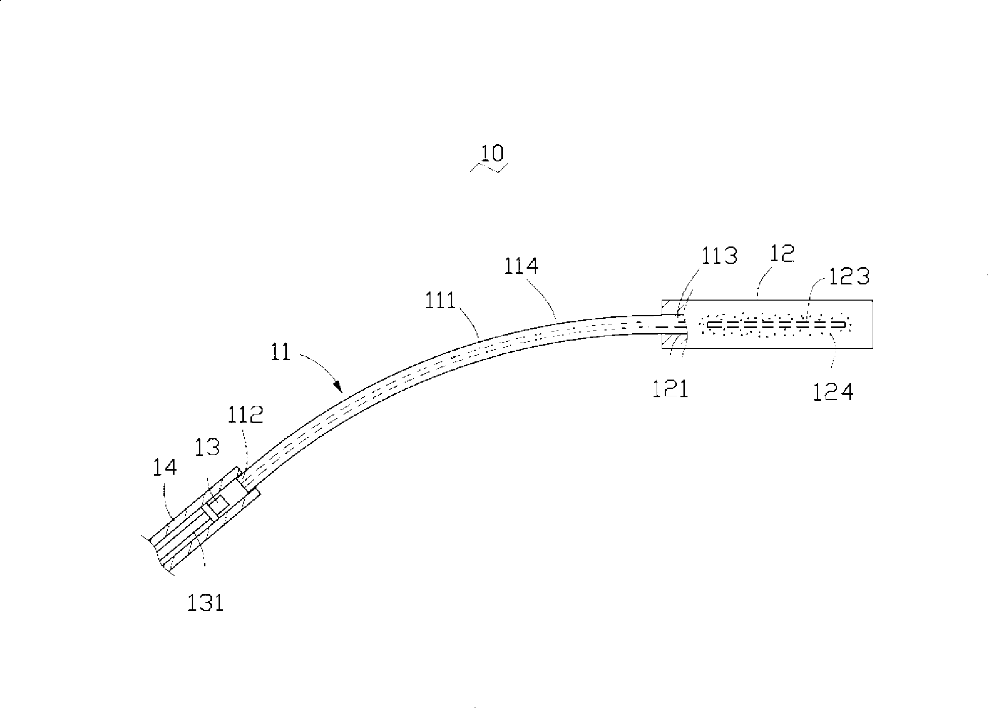
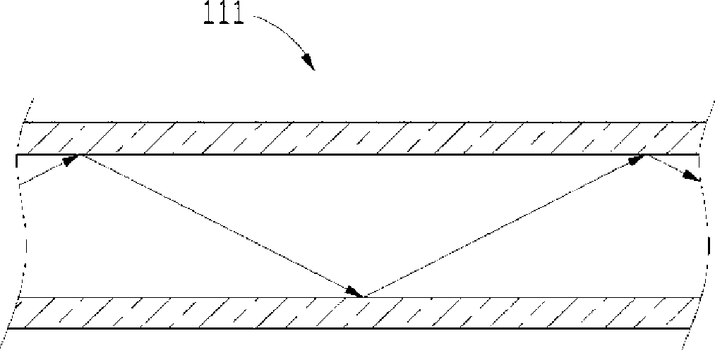
[0019] figure 1 Shown is a schematic structural view of the first embodiment of the oral lighting device of the present invention. The oral lighting device 10 includes a solid-state light-emitting element, a light-conducting fiber 111 and a light-guiding body 12, and the light-conducting fiber 111 is arranged on the solid-state light-emitting device. Between the element and the light guide 12. The light-conducting fiber 111 has a light-incident end 112 and a light-exit end 113. The solid-state light-emitting element and the light guide 12 are respectively optically coupled to the light-incidence end 112 and the light-exit end 113 of the light-conducting fiber 111. The solid-state light-emitting element emits The light reaches the light guide body 12 through the light guide fiber 111 , and is emitted by the light guide body 12 .

[0020] In this embodiment, the solid-state light-emitting element is a light-emitting diode 13 (LED). The light-emitting diode 13 has the characteri...


PUM


Abstract

An oral cavity lighting device comprises a solid-state light-emitting component, a light conducting fiber and a light conductor, wherein the light conducting fiber is provided with a light incident end and a light emergence end; the solid-state light-emitting component and the light conductor are respectively and optically coupled with the light incident end and the light emergence end of the light conducting fiber; the oral cavity lighting device can further comprise a hanger, through which the oral cavity lighting device can be hung in the positions of the mouth of the patient, etc. The light conductor is detachably connected with the oral cavity lighting device. The oral cavity lighting device provided by the invention can avoid the solid-state light-emitting components which provides the light source and the conducting wires to directly come into the mouth of the patients and prevent the short circuit caused by the humid environment inside the oral cavity; the light conductor can provide a large-scale lighting area, improve the multi-angled and high-brightness lighting inside the oral cavity and can not be easily shielded. Moreover, the light conductor is detachable and can be displaced after being used, which is beneficial for the disinfection and sterilization for the oral cavity lighting device after the patients are cured and the diseases infections among the patients can be avoided.

Description

technical field [0001] The invention relates to an oral cavity lighting device, in particular to an oral cavity lighting device which can provide sufficient illumination in the patient's oral cavity. Background technique [0002] Dentists need to provide enough light to the inside of the patient's oral cavity during dental surgery to facilitate illumination and identification of the tooth structure inside the oral cavity, and then perform inspections, operations and other operations. The commonly used light source method for dentists to treat patients is to use diffused standing lamps to irradiate the inside of the patient's mouth. However, because the light source is far away from the patient's mouth, it is easily blocked by the doctor's or assistant's head or hands and other body parts, resulting in shadows incident on the patient's mouth. The interior of the patient's mouth is not getting enough light. Generally, the light source of dental lighting is an incandescent tun...

Claims


Application Information

Patent Timeline
Patent Type & Authority Applications(China)
IPC IPC(8): F21V8/00A61B1/24A61B1/07F21V5/04F21V5/00F21W131/20F21Y101/02
CPCA61B1/07A61B1/24A61B1/0653A61C1/088A61B1/0684
Inventor 徐智鹏李泽安
Owner FOXSEMICON INTEGRATED TECHNOLOGY (SHANGHAI) INC
Why Eureka
Try Eureka