
Weft laying trolley of warp knitting machine

A technology of weft laying trolley and warp knitting machine, applied in warp knitting, textiles, papermaking, knitting, etc., can solve the problems of waste, poor frame stability, difficult processing, etc.

Inactive Publication Date: 2009-06-17
CHANGZHOU RUNYUAN WARP KNITTING MACHINERY
View PDF0 Cites 1 Cited by
  • Summary
  • Abstract
  • Description
  • Claims
  • Application Information

AI Technical Summary

Problems solved by technology

The weft laying trolley with this structure, on the one hand, because the guide rod seat and the side plate are integral castings, the part occupies a large space and is heavy, and because the castings often have shrinkage cavities and sand inclusions during the casting process And other defects, thus making this part not only difficult to process, but also high production cost and scrap rate, installation and maintenance are also very inconvenient. When the guide rod shaft hole in the guide rod seat cannot be used due to wear, the guide rod must be replaced. The seat and the side plates are scrapped together, resulting in greater waste; on the other hand, since the top plate and the side plates are connected by bolts to form the frame of the trolley, and the frame stability of this structure is poor, and vibrations often occur during the weft laying process Phenomenon, affecting the precision of weft laying

Method used


Image

  • Weft laying trolley of warp knitting machine
  • Weft laying trolley of warp knitting machine
  • Weft laying trolley of warp knitting machine

Examples


Embodiment Construction

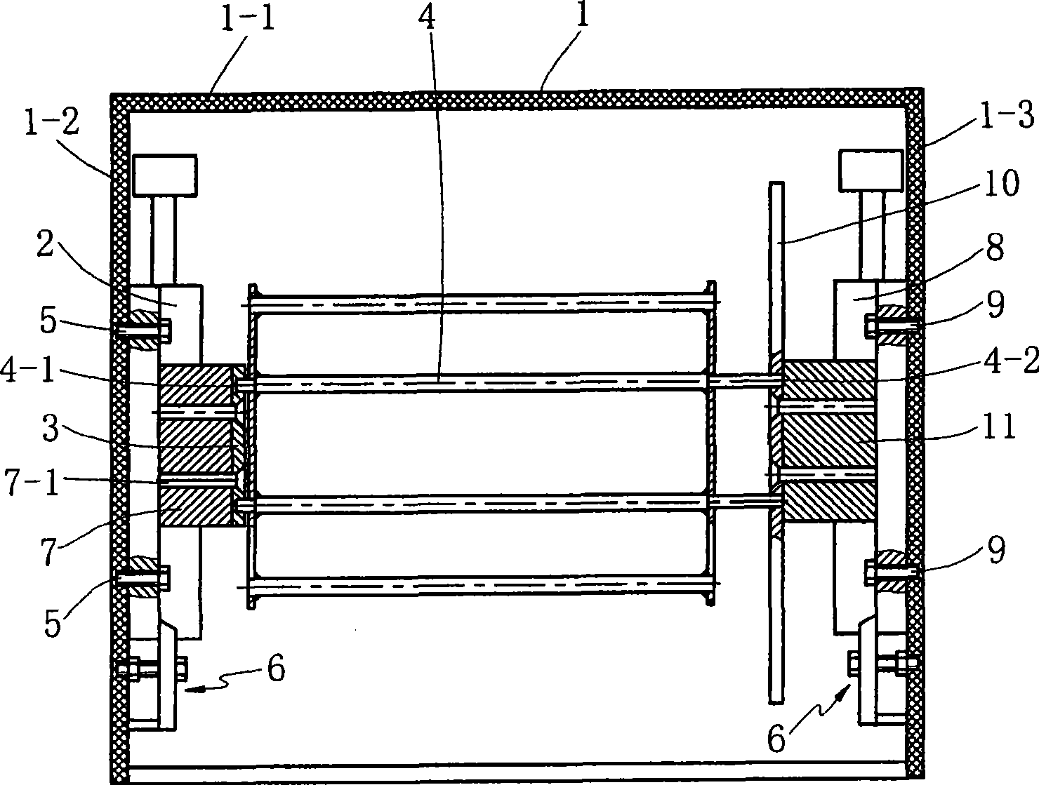
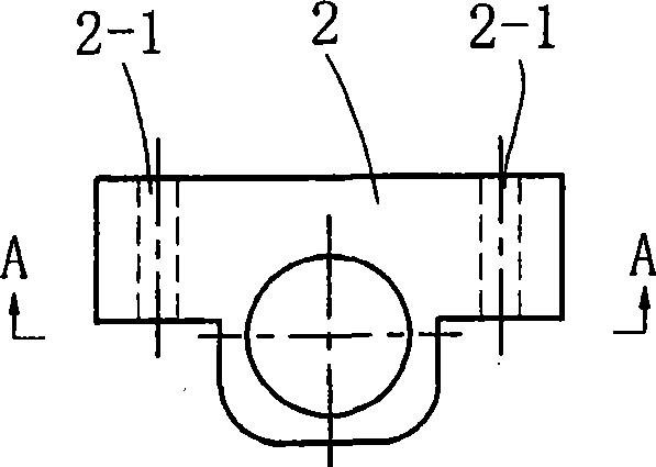
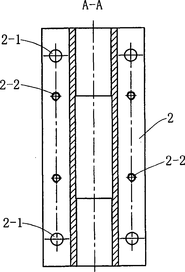
[0013] See Figure 1 to Figure 3 , A warp knitting machine weft laying trolley, comprising a trolley frame 1 composed of a top plate 1-1 and two side plates 1-2, 1-3, a first plate located on one side plate 1-2 of the inner cavity of the trolley frame 1 A guide rod seat 2, a first tension rod seat 3 fixedly connected to the first guide rod seat 2, and a tension rod 4, one end 4-1 of the tension rod 4 is rotatably connected with the first tension rod seat 3 , The first guide rod seat 2 is detachably connected to the side plate 1-2 of the inner cavity of the trolley frame 1.

[0014] The first guide rod seat 2 penetrates the bolt 5 through its hole 2-1 or through the plate bolt mechanism 6 provided at the upper and lower parts of the first guide rod seat 2 and the inner cavity side plate 1- of the trolley frame 1 2 constitute a detachable connection.

[0015] In order to simplify the structure of the first guide rod seat 2 and facilitate the connection between the first tension rod s...


PUM


Abstract

The invention discloses a weft thread spreading pony truck of a warp knitting machine. The weft thread spreading pony truck comprises a pony truck frame formed by a head plate and two side plates, a first guide rod pedestal arranged on one side plate of the inner cavity of the pony truck frame, a first tension rod pedestal permanently connected with the first guide rod pedestal and a tension rod. One end of the tension rod is rotationally connected with the first tension rod pedestal, and the first guide rod pedestal is detachably connected with one side plate of the inner cavity of the pony truck frame; the other side plate of the inner cavity of the pony truck frame is also detachably connected with a second guide rob pedestal; a second tension rod pedestal is arranged between the second guide rod pedestal and the tension rod, the second tension rod pedestal is permanently connected with the second guide rod pedestal, and the other end of the tension rod is rotationally connected with the second tension rod pedestal; and the head plate and the two side plates forming the pony truck frame can be integrated into a whole part. The invention has the advantages that the processing is convenient, the production cost is low, the occupied space is small, yarns receive strength evenly, and the quality of spreading weft thread is good, thus having good commercial prospect.

Description

Technical field [0001] The invention relates to a component in a weft laying mechanism of a warp knitting machine, in particular to a weft laying trolley for a multi-axial warp knitting machine. Background technique [0002] At present, warp knitting machines, especially the weft laying trolley in the weft laying mechanism of multi-axial warp knitting machines, include a trolley frame composed of a top plate and two side plates, a guide rod seat on one side plate of the inner cavity of the trolley frame, and A tension rod seat fixedly connected to the guide rod seat and a tension rod, one end of the tension rod is rotatably connected with the tension rod seat, the guide rod seat and the side plate of the inner cavity of the trolley frame are an integral casting, and the trolley The top plate and the side plates of the frame are separated and connected by bolts to form the trolley frame. The weft laying trolley with this structure, on the one hand, because the guide rod seat and t...

Claims


Application Information

Patent Timeline
IPC IPC(8): D04B27/00D04B27/10
Inventor 王占洪刘莉萍黄骏肖叶
Owner CHANGZHOU RUNYUAN WARP KNITTING MACHINERY
Learn More