Method for determining engine crankshaft position

A crankshaft position and engine technology, applied in engine control, machine/engine, mechanical equipment, etc., can solve problems such as inability to accurately determine the crankshaft reversal and the angle of reversal, and inability to accurately determine the stop position of the crankshaft.

Active Publication Date: 2009-06-17
CHERY AUTOMOBILE CO LTD
View PDF0 Cites 11 Cited by
  • Summary
  • Abstract
  • Description
  • Claims
  • Application Information

AI Technical Summary

Problems solved by technology

[0004] In short, the existing technology cannot accurately determine whether the crankshaft is reversed and the angle of the reversed direction, nor can it accurately determine the stop position of the crankshaft

Method used


Image

  • Method for determining engine crankshaft position
  • Method for determining engine crankshaft position
  • Method for determining engine crankshaft position

Examples


Embodiment Construction

[0034] The present invention will be described in detail below according to the accompanying drawings, which is a preferred embodiment among various implementations of the present invention.

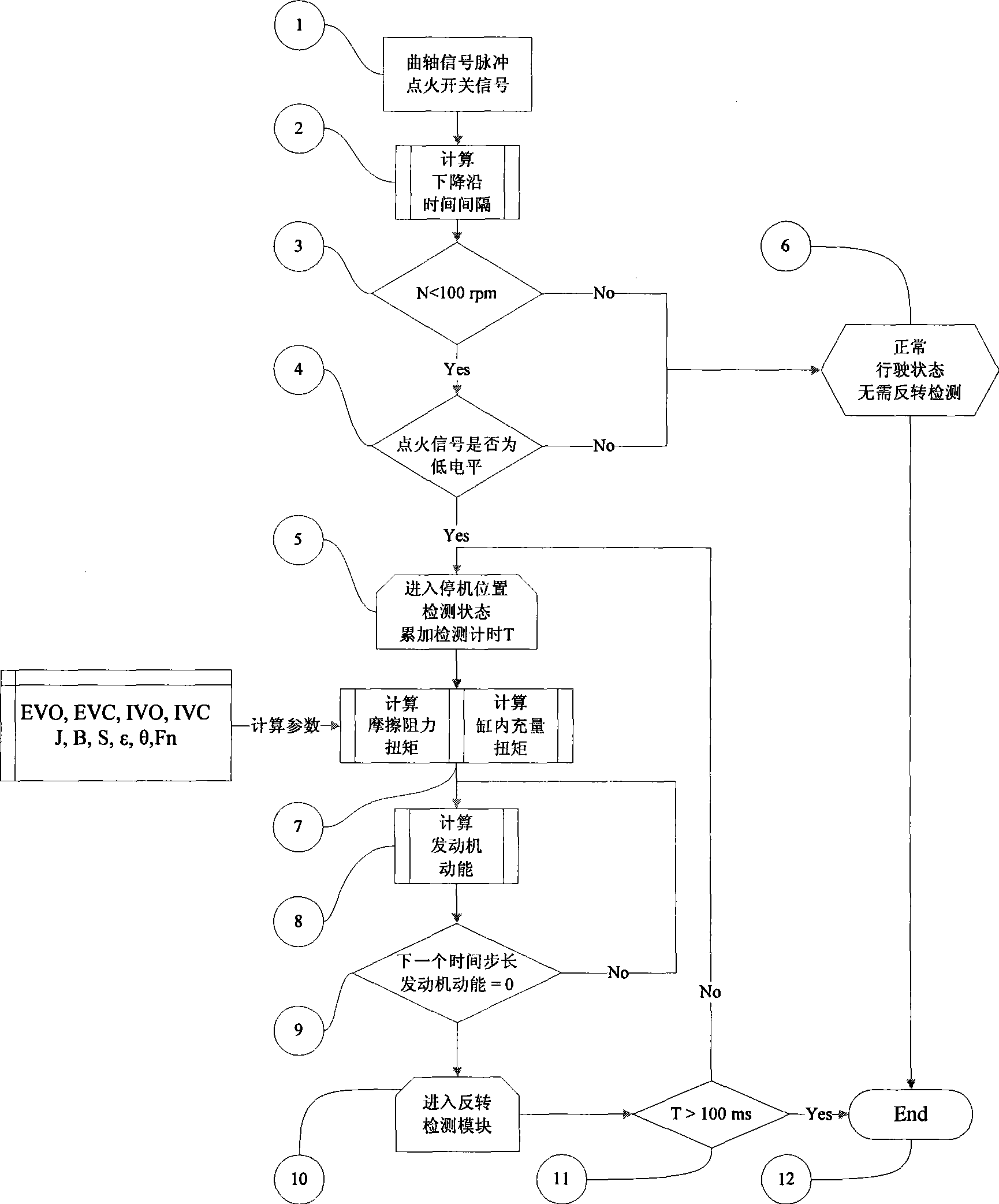
[0035] figure 1 It is each step of the present invention to detect the crankshaft position of the engine in the shutdown process.

[0036] In step 1, input the most important judgment signals of this method: crankshaft position signal pulse and ignition switch state. In step 2, the time interval of the crankshaft position signal pulse is calculated according to the falling edge, and the engine speed is calculated. In step 3, it is judged whether the engine speed enters the shutdown critical condition. If the speed is less than 100 RPM, the output is YES, continue to step 4. If the rotational speed is greater than or equal to 100 revolutions per minute, output No, go to step 6, enter the normal driving state, and do not perform reverse detection.

[0037] In step 4, it is another cond...


PUM


Abstract

The invention relates to a method for detecting the position of an engine crankshaft. Under the condition of using an original non-directional crank position judgment sensor, on the basis that the concepts of engine friction torque and inner cylinder charging torque are introduced, and the variation tendency of the engine dynamic power is calculated; on the moment that all dynamic power are zero, the crankshaft inverse rotation position can be probably generated, and by checking the pulse interval of rotational speed signals before and after the probable inverse rotation point, whether the inverse rotation is generated or not and the concrete time of the inverse rotation are finally determined. The method can judge the switching number of the rotation direction of the crankshaft in the shutdown process to the utmost extent and can determine rotated angles in different rotation directions, so that the stop position of the engine crank is finally determined accurately.

Description

technical field [0001] The invention relates to a method for detecting the position of an engine crankshaft, in particular to a method for predicting the position of the crankshaft during engine shutdown. Background technique [0002] Engine crankshaft position detection and signal synchronization are the basis of engine fuel injection and ignition control, especially in the engine starting process, the earlier the engine controller judges the crankshaft position, the better the starting quality and the lower the emission during the starting process. The engine controller detects the signal triggered by the crankshaft position signal wheel through the engine crankshaft sensor, which constitutes the most basic signal logic basis for engine operation control. The accurate position of the last run and stop is memorized in the volatile memory, so that the engine controller can shorten the judging time of starting synchronization, that is, shorten the angle that the crankshaft ro...

Claims


Application Information

Patent Timeline
Patent Type & Authority Applications(China)
IPC IPC(8): F02D41/06
Inventor 周重光吴培周苏万樯
Owner CHERY AUTOMOBILE CO LTD
Why Eureka
Try Eureka